Maximizing PEM fuel cell power plant system efficiency at optimum system pressure

Inactive Publication Date: 2003-10-30
INT FUEL CELLS
View PDF1 Cites 5 Cited by
  • Summary
  • Abstract
  • Description
  • Claims
  • Application Information

AI Technical Summary

Benefits of technology

0006] Objects of the invention include provision of a PEM fuel cell power plant: which operates at or near maximum system efficiency; which operates at a system pressure which provides overall maximum system efficiency, taking into account thermodynamic

Problems solved by technology

In particular, utilizing electricity generated by the fuel cell power plant to operate the pump (fan, blower or compressor) which provides the process air to the fuel cell power plant comprises a significant load of parasitic power consumption.
It has heretofore been known that a fuel cell power plant operating at or near am

Method used


Image

  • Maximizing PEM fuel cell power plant system efficiency at optimum system pressure
  • Maximizing PEM fuel cell power plant system efficiency at optimum system pressure
  • Maximizing PEM fuel cell power plant system efficiency at optimum system pressure

Examples


Embodiment Construction

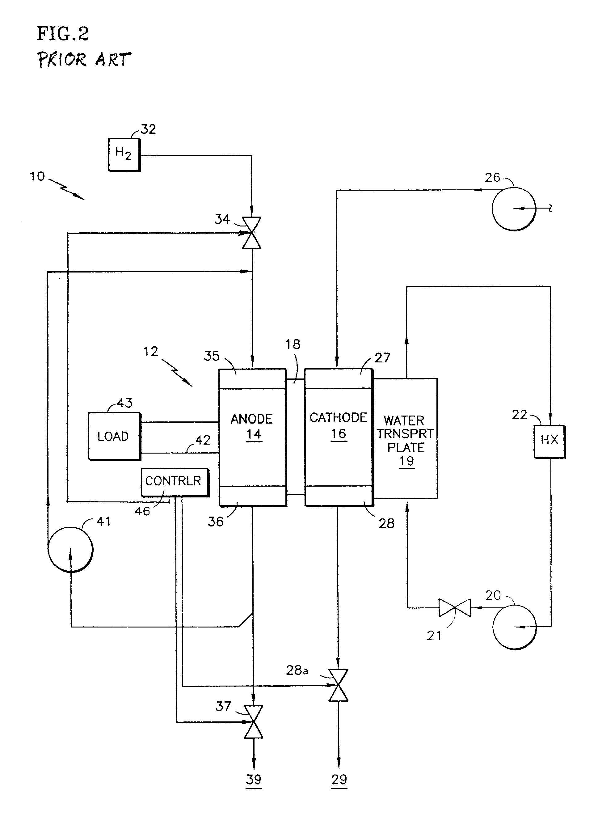
[0018] Referring to FIG. 2, a fuel cell power plant 10 includes a cell stack assembly 12 which comprises a plurality of individual fuel cells stacked together in contiguous relationship, although only a single cell is illustrated in FIG. 1. A fuel cell includes an anode electrode 14, a cathode electrode 16, and a polymer electrolyte membrane 18 disposed between the electrodes. Each electrode consists of a catalyst, a porous support plate and a reactant flow field as is well known. A water transport plate 19 (or coolant plate), adjacent to the cathode 16, is connected to a coolant control loop including a coolant pump 20, a coolant pressure control valve 21, and a heat exchanger 22. There may be a heat exchange bypass and other water management apparatus, not shown, as disclosed in U.S. Pat. No. 5,503,944. The pump 20 and valve 21 will regulate both the pressure and the volume of flow through the water transport plate 19 and through (or around) the heat exchanger 22. Air is supplied ...


PUM


Abstract

A PEM fuel cell power plant system (10) has a process air pump (26), which may be a fan, a blower or a compressor, with an adiabatic efficiency of between 40% and 70%. The process air at the inlet 27 of the cathode reactant gas flow field 16 is between 1.07 atmospheres and 1.85 atmospheres, and may be at an optimal pressure for maximum overall system efficiency P={0.45+2.6E-1.8E<2>}atms±0.2 atms where P is the air inlet pressure and E is the adiabatic efficiency of the process air pump.

Description

[0001] This invention relates to operation of a proton exchange membrane (PEM) fuel cell power plant at a pressure which is selected to correspond with the adiabatic efficiency of the reactant air pump.[0002] Heretofore, one type of PEM fuel cell power plant utilizes compressors to pump the reactant air to the cathode reactant gas flow fields, and has typically been operated with air inlet pressures of two or three atmospheres. This takes advantage of the ability of a fuel cell to operate at higher average cell temperatures, exhaust dew point temperatures and coolant temperatures as a consequence of higher operating pressures. Another type of known fuel cell power plant may utilize a fan or blower to provide the reactant air, and consequently works near ambient pressure. While this type of fuel cell power plant cannot take advantage of the efficiencies that result from higher pressure and therefore higher temperature, the overall system efficiency is higher than that of the fuel cel...

Claims


Application Information

Patent Timeline
IPC IPC(8): H01M8/10H01M8/00H01M8/04
CPCH01M8/04089H01M8/04097Y02E60/50H01M8/1002H01M8/04291H01M8/1007H01M8/04H01M8/10
Inventor SESHADRI, PARTHASARATHYMEYER, ALFRED P.VAN DINE, LESLIE L.CLARK, THOMAS M.
Owner INT FUEL CELLS
Why Eureka
Try Eureka