
Automatic emergency shut-off system for delivery transports

a delivery and automatic technology, applied in the field of automatic shut-off systems, can solve problems such as inability to maintain the pressure in the system, and inability to detect leakag

Inactive Publication Date: 2003-11-13
BR&T TECH DEV CORP
View PDF0 Cites 14 Cited by
  • Summary
  • Abstract
  • Description
  • Claims
  • Application Information

AI Technical Summary

Benefits of technology

0028] FIG. 1 is a schematic representation of the preferred automatic safety shut-off system.
0029] FIG. 2 is a diagram of the preferred main control unit.
0030] FIG. 3 is a diagram of the preferred hand held interface.
0031] FIG. 4 is a diagram of the preferred remote control unit.

Problems solved by technology

In the delivery of hazardous liquids or volatile fuels a leak can occur in the delivery hose and the delivery personnel are unable or unwilling to control and shut down the system thereby causing environmental concerns and harm to life through fire, explosion, or other dangerous conditions.
Such systems are unable to detect a leak until it has become so major that the pump can no longer maintain the pressure in the system at which time an alarm is triggered.
The methods employed are mechanical in nature and are relatively inflexible and unintelligent.
For example, a small hose leak would be indiscernible in a fixed point system.
It is during this time that a leak may occur in the delivery system.
The connection could come loose, the hose could rupture or a small leak could occur due to wear on the hose.
The time required to perform these tasks permits the loss of rapidly expanding volatile gas.
Current systems are relatively inflexible in their implementation.
The systems do not and cannot operate dynamically taking variable conditions under consideration.
Operators fear the result of a propane leak and may abandon a leaking vehicle instead of stopping the leak.
In the case where the delivery pump is a constant velocity type the system is limited in its ability to increase flow once set.

Method used


Image

  • Automatic emergency shut-off system for delivery transports
  • Automatic emergency shut-off system for delivery transports
  • Automatic emergency shut-off system for delivery transports

Examples


example

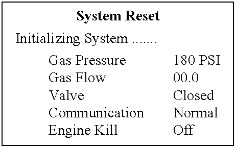
[0053] Assuming that an automatic shut off system has been installed on a liquid propane gas commercial delivery vehicle and MCU 28 is installed in the cab of the vehicle, HHI 26 is attached to MCU 28 by a flexible cable and RCU 24 is mounted at the rear of the vehicle.

[0054] The owner / operator of the vehicle has provided the driver with a delivery itinerary and the truck has been loaded with the appropriate amount of fuel for the day's deliveries. All safety checks have been made and the equipment is ready for the driver.

[0055] Under normal operating conditions and while the vehicle is off duty, ball valve 16 is in a closed position. After normal delivery and without operator intervention ball valve 16 will be closed automatically by the actuator 30 within a preset time limit. MCU 28, HHI 26, and RCU 24 obtain electrical resources from the 12 Volt system of the host vehicle. An internal battery can supply power to maintain the current date and time for the system. The electronics o...


PUM

PropertyMeasurementUnit
volatileaaaaaaaaaa
timeaaaaaaaaaa
pressureaaaaaaaaaa

Abstract

A software driven, solid state controlled, electro-mechanically operated system to monitor volatile liquid fuel or other hazardous liquids and provide emergency shut-off if the delivery system is ruptured. A computer receives input from transducers monitoring the flow rate of the liquid through the line and a pressure sensor insures the system is prepared to function. The monitoring apparatus presets a condition based on current environmental conditions. Measuring the flow rate provides input to software that validates all other entries. Delivery quantities allowing point of delivery control to vary the delivery quantity to individual locations. The software options are: Preset conditions; Owner / operator input via external computer for loading delivery and trip instructions; Instructional output on LCD screen to driver on customer information and scheduling; Data download to owner / operator on billing information, driver daily activities and volume of propane remaining in vehicle.

Description

[0001] 1. Field of the Invention (Technical Field)[0002] The present invention relates to electronic measurement and control, and more particularly to a method and apparatus to monitor the dispensing of caustic liquids or volatile liquid fuels and automatically terminate the dispensing process without human intervention in cases where the dispensing line leaks or breaks.[0003] 2. Background Art[0004] In the delivery of hazardous liquids or volatile fuels a leak can occur in the delivery hose and the delivery personnel are unable or unwilling to control and shut down the system thereby causing environmental concerns and harm to life through fire, explosion, or other dangerous conditions.[0005] Current methods employ a means to monitor the dispensing process for liquid propane gas, for example, by focusing on the pressure in the delivery system. Delivery trucks are typically equipped with constant velocity pumps that provide a constant flow of fuel to the destination tank under the dr...

Claims


Application Information

Patent Timeline
Patent Type & Authority Applications(United States)
IPC IPC(8): B67D7/32
CPCB67D7/3218Y10T137/7726
Inventor COTHERN, TONY J.BINDL, RONALD H.CRAIG, RODNEY O.CREAM, DONFREEMAN, GEORGE B.
Owner BR&T TECH DEV CORP
Learn More