Coordinate registration system for dual modality imaging systems

a dual-mode imaging and registration system technology, applied in the field of coordinate registration system for dual-mode imaging systems, can solve the problems of difficult to provide and maintain the required accuracy of coincidence of the fov coordinate system of the scanner's imaging subsystems, and in general not provide well defined images of the structural anatomy of the patient's body, so as to improve the quality of fused images

Inactive Publication Date: 2003-11-13
ELGEMS
View PDF13 Cites 49 Cited by
  • Summary
  • Abstract
  • Description
  • Claims
  • Application Information

AI Technical Summary

Benefits of technology

[0010] An aspect of some embodiments of the present invention relates to improving quality of fused images provided by a DM scanner comprising a first and a second imaging subsystem.
[0017] In accordance with some embodiments of the present invention, the position of at least one of the first and second imaging subsystems is adjusted to reduce an alignment displacement between the first and second FOV coordinate systems.
[0020] Optionally, fiducial regions imaged by the first system are imaged by the second system. Optionally, determining positions of features comprises determining the coordinates to accuracy better than a resolution of an imaging system of the first and second imaging systems having a lowest resolution. Optionally, determining positions of features comprises determining positions for a center of mass for each of the fiducial regions. Optionally, the first and second imaging systems comprise means for adjusting the position of at least one of the systems and comprising controlling the adjustment means responsive to at least one of the determined linear and angular displacements to reduce the at least one displacement.

Problems solved by technology

While providing generally satisfactory spatial images of concentrations of a radionuclide in a patient's body, nuclear imaging modalities do not in general provide well defined images of the structural anatomy of the patient's body.
As a result, a spatial map of the concentration of a radionuclide in a patient provided by a nuclear imaging modality does not in general provide an accurate location of the concentration relative to the morphology of the patient's body.
In general, as a result for example, of changes in the ambient environment of a DM scanner, vibrations and variable temperature gradients in the scanner, it is often difficult to provide and maintain the required accuracy of coincidence of the FOV coordinate systems of the scanner's imaging subsystems.
As a result, quality of fused images provided by a DM scanner is often compromised.

Method used


Image

  • Coordinate registration system for dual modality imaging systems
  • Coordinate registration system for dual modality imaging systems
  • Coordinate registration system for dual modality imaging systems

Examples


Embodiment Construction

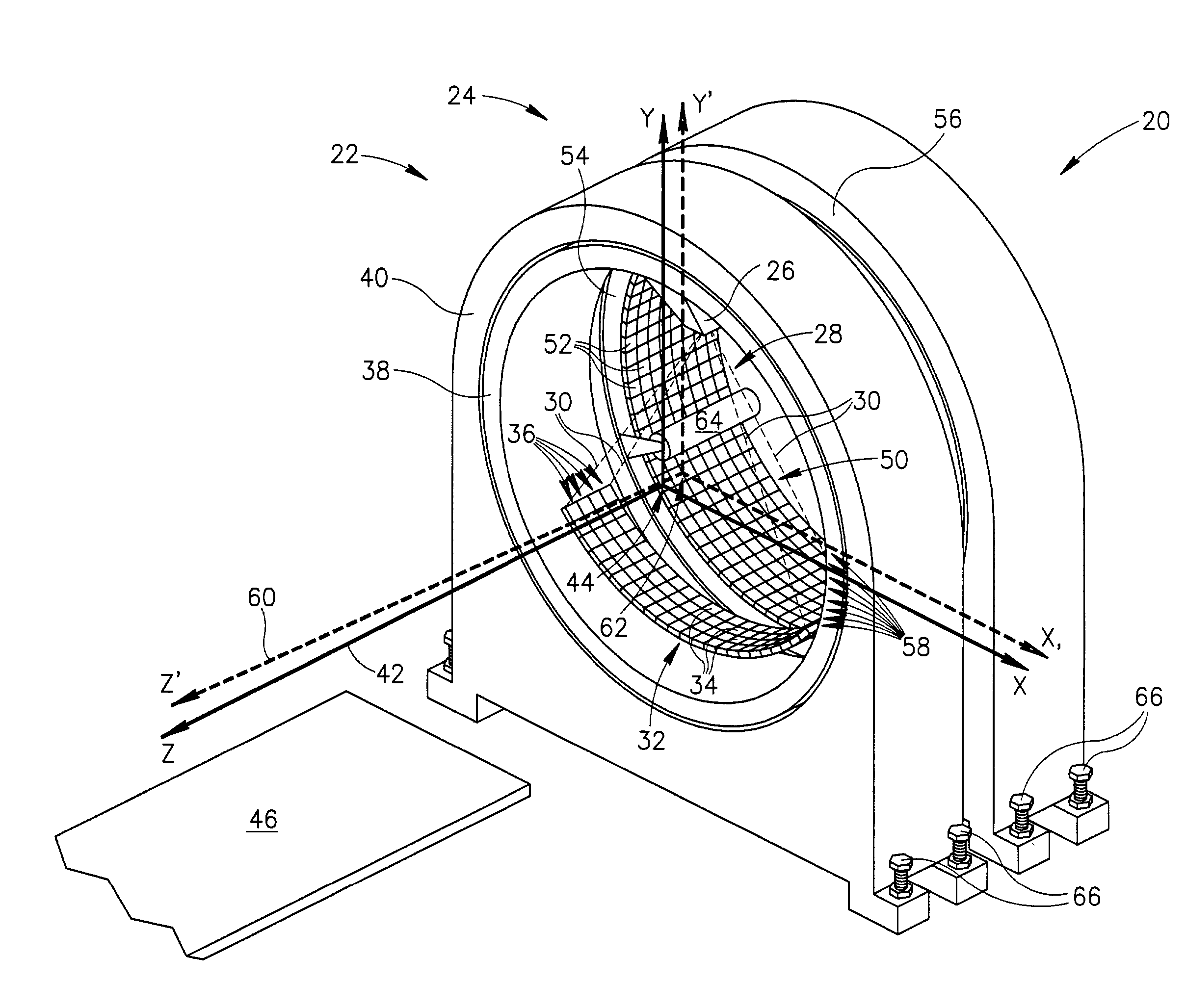
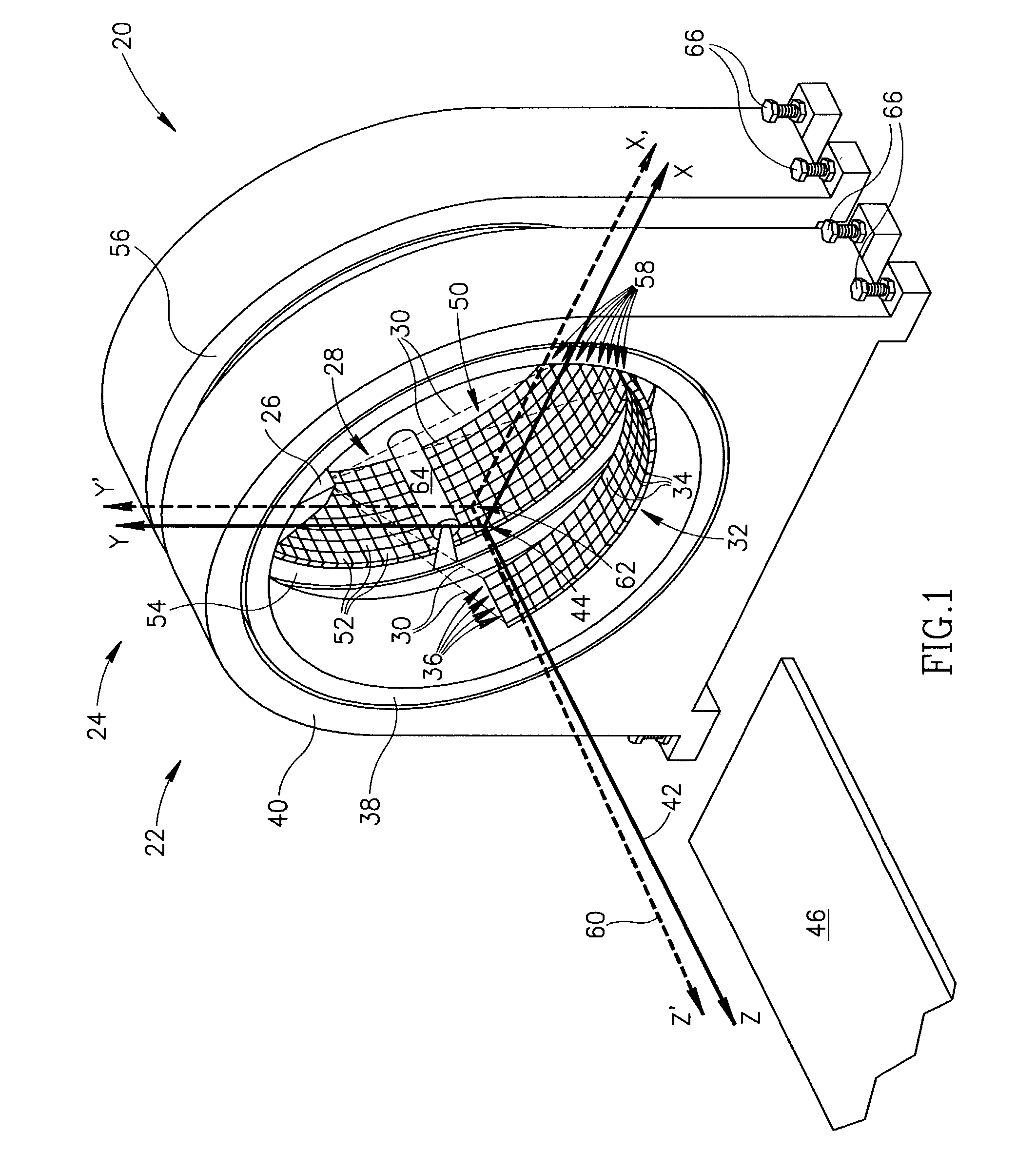
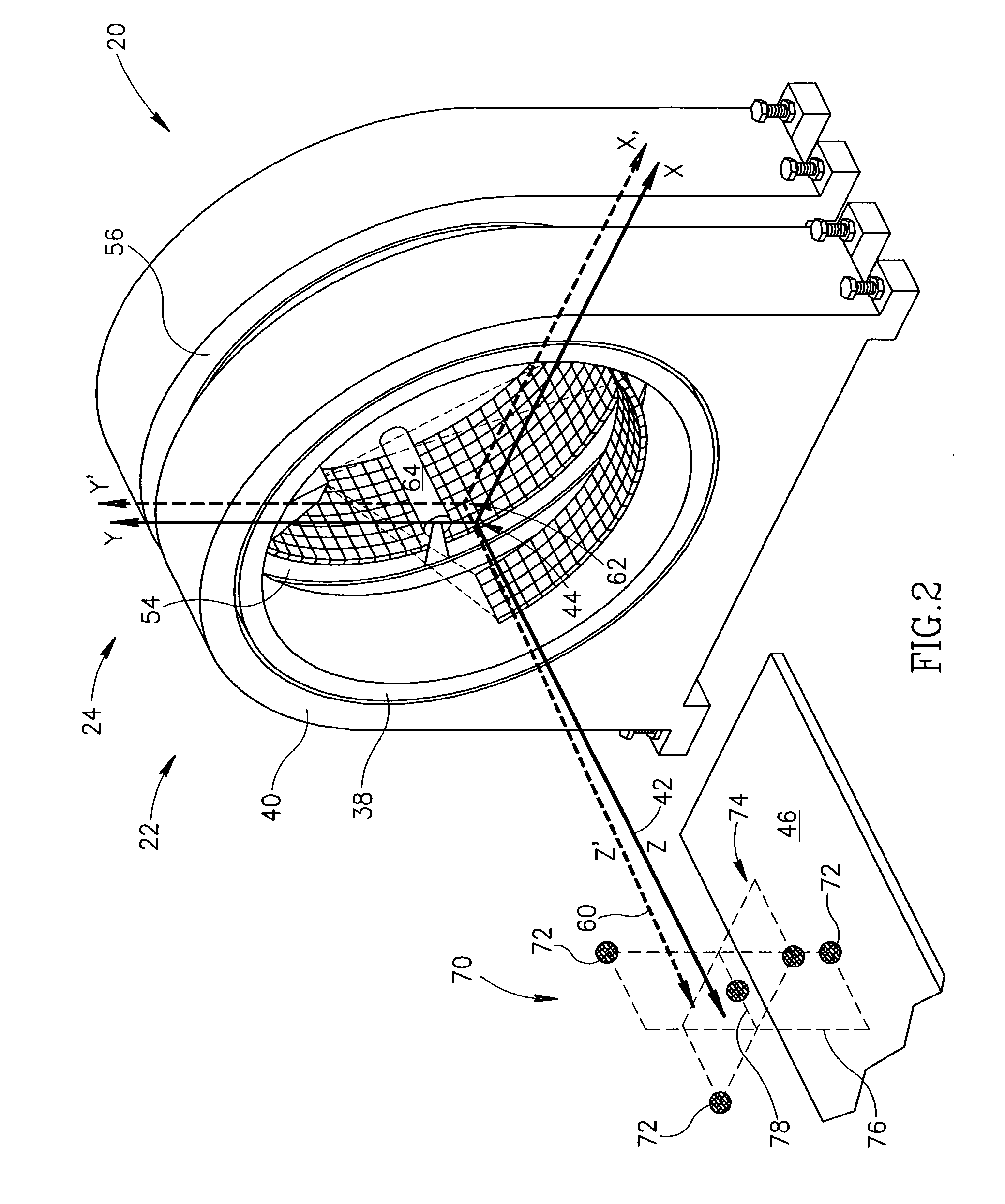
[0030] FIG. 1 schematically shows a DM scanner 20 comprising, by way of example, a CT imaging subsystem 22 and a nuclear imaging subsystem 24 which may be a PET, SPECT or PET and SPECT imaging subsystem. Hereinafter it is assumed that imaging subsystem 24 may function as both a PET and SPECT nuclear imager and is referred to as PET-SPECT imaging subsystem 24. Nuclear imaging systems that can function as both PET and SPECT imagers are known in the art. Examples of PET-SPECT imaging systems are found in U.S. Pat. No. 6,255,655 and U.S. Pat. No. 6,303,935. DM scanner 20 fuses images of a patient provided by CT subsystem 22 and PET-SPECT subsystem 24 to provide a fused image of the patient showing concentration of a radiopharmaceutical in the patient's body relative to the structural anatomy of his or her body. Only elements and features of DM scanner 20 and its subsystems 22 and 24 that are germane to the discussion are shown in FIG. 1.

[0031] CT imaging subsystem 22 comprises an X-ray ...


PUM


Abstract

A method of determining linear and angular displacements of a first coordinate system of a field of view of a first imaging system relative to a second a coordinate system of a field of view of a second imaging system, the method comprising: providing a phantom having a plurality of fiducial regions that can be imaged by both imaging systems; acquiring first and second images of the phantom with the first and second imaging systems wherein spatial coordinates of features in the first and second images reference the first and second coordinate systems respectively; determining positions of a plurality of features of the fiducials in the first image and spatial coordinates of the same features in the second image; and using the coordinates to determine the linear and angular displacements.

Description

[0001] This application claims priority under 35 U.S.C. .sctn. 119(e) to U.S. Provisional Patent Application No. 60 / 325,580, filed on Oct. 1, 2001, titled "Device and Method of registration for Combined Diagnostic Imaging System," incorporated herein by reference in its entirety.[0002] The invention relates to imaging systems that employ a plurality of modalities for imaging a patient and in particular to apparatus and methods for registering the fields of view of different sub-systems in the system that image the patient with the different modalities.[0003] In nuclear imaging a radiopharmaceutical that emits radiation is introduced into a patient's body and radiation emitted by the radiopharmaceutical is detected to determine where and in what amounts the radiopharmaceutical concentrates in the body. Depending upon the particular application and pharmaceutical introduced, the detected concentration may be used to generate images of organs and features of the body, or provide functi...

Claims


Application Information

Patent Timeline
Patent Type & Authority Applications(United States)
IPC IPC(8): A61B6/00A61B6/03
CPCA61B6/032A61B6/583A61B6/5235A61B6/037
Inventor WILK, MICHAELHAJAJ, BINYAMINLUYBANSKY, MICHAELALTMAN, HERNAN
Owner ELGEMS
Why Eureka
Try Eureka