Engine cooling system and method for making same

a technology for cooling systems and engines, applied in the direction of machines/engines, mechanical equipment, light and heating equipment, etc., can solve the problems of significant heat generation of engines, significant reduction of engine power output, so as to achieve enhanced cooling effect and efficient transfer of heat to the environment

Inactive Publication Date: 2003-11-20
BRINTON KEITH A
View PDF0 Cites 4 Cited by
  • Summary
  • Abstract
  • Description
  • Claims
  • Application Information

AI Technical Summary

Benefits of technology

[0014] In contrast to conventional cooling fins of an engine, or a component thereof, the cooling system of the present invention includes at least a portion of at least one edge of a fin being provided with at least one, and preferably a plurality of pre-selectively configured concavities, or incisive voids, so as to form an intaglio to enable the fin to transfer heat to the environment more efficiently and thus provide an enhanced cooling effect as compared to conventional cooling fins. The present invention, in a preferred embodiment, comprises engraving at least the edge surface of a fin of an engine, or component thereof, with a rotatable engraving tool, or cutting tool, to provide a plurality of pre-selectively configured concavities preferably arranged in preselected, repeating pattern.

Problems solved by technology

Engines, especially internal combustion engines, produce significant amounts of heat during the course of their operation.
Failure to transfer heat away from the engine can result in a significantly reduced power output of the engine and in extreme conditions could lead to failure of the engine.
Such air-cooled engines are, for example, used extensively to power motorcycles, snowmobiles, light aircraft, and other vehicles where the weight and added complexity of a liquid-cooled engine is not desired or feasible.

Method used


Image

  • Engine cooling system and method for making same
  • Engine cooling system and method for making same
  • Engine cooling system and method for making same

Examples


example

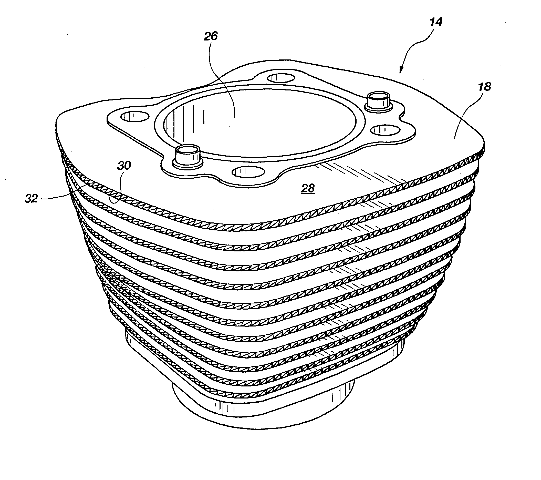
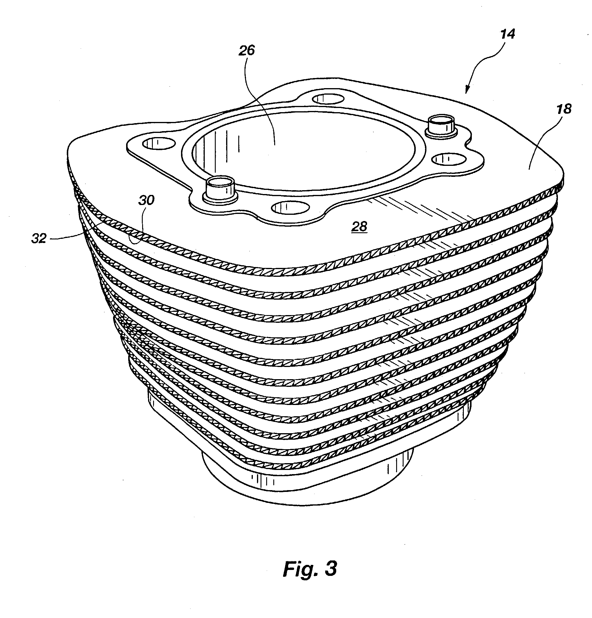
[0056] A cylinder, having an individual displacement of 670 cc, and an attached cylinder head of a V-twin motorcycle engine having a total displacement of 1340 cc was tested. The upright edges of the cylinder as well as the upright edges of the cylinder head exhibited were configured according to the preferred embodiment of the instant invention as shown in FIGS. 19-24, i.e. the upright edges were engraved to define a plurality of elongate concavities. Each of the concavities was oriented with its longitudinal axis at an acute angle to the longitudinal axis of the surface of the edge. The edges were fitted with Omega K-type thermocouples. The thermocouples were attached to the edges with high thermal conductive adhesive. The thermocouples were attached to the 7.sup.th fin and the 13.sup.th fin at mid span on the rear of the cylinder and cylinder head arrangement. A thermocouple was also attached to the 13.sup.th fin on the right side of the arrangement, in a central region of the ri...


PUM


Abstract

Engine cooling system and method for making same wherein an engine, engine casing, or component thereof or a component related thereto has at least one cooling fin (18) having at least a portion of an edge surface (32) including an engraved, or intagliated portion (40). Preferably the surface edge includes a plurality of itagliated portions (40) with each portion including at least two elongated concavities being in preselected orientation and relationship to each other to improve the cooling efficiency of the fin and thus allow the engine to operate in wider, more extreme range of temperatures and environments. The present invention is particularly well suited, but not limited to air-cooled engines and related components such as component covers, inspection / access covers, and oil coolers and is therefore readily adaptable to engines used to propel motor vehicles such as, but not limited to, motorcycles.

Description

[0001] This application is a continuation of U.S. application Ser. No. 10 / 049,244 filed Jun. 3, 2002, presently pending, which is a national entry application under 35 U.S.C. 371 et seq. of PCT Application No. PCT / US00 / 20535 filed Jul. 27, 2000 and published in English on Feb. 1, 2001, which claims priority under 35 U.S.C. 120 to U.S. application Ser. No. 09 / 361,325 filed 27 July 1999, now abandoned.[0002] The present invention relates generally to engines, including but not limited to internal combustion engines used, for example, as source of power in propelling motorized vehicles. Specifically, the invention is directed to a cooling system for engines and components thereof as well as methods for producing the system.[0003] Engines, especially internal combustion engines, produce significant amounts of heat during the course of their operation. Continued operation of an engine requires that the heat produced during its operation be transferred away from the engine at a high rate....

Claims


Application Information

Patent Timeline
Patent Type & Authority Applications(United States)
IPC IPC(8): F01P1/02F02B61/02F02B75/18F02B75/22F28F1/24F28F13/18
CPCF01P1/02F02B61/02F28F13/18F02B2075/1808F28F1/24F02B75/22
Inventor BRINTON, KEITH A.
Owner BRINTON KEITH A
Why Eureka
Try Eureka