Abnormality detector for a motor drive system

a motor drive system and detector technology, applied in the direction of electrical control, electrical control, electric programme control, etc., can solve the problems of difficult maintenance work, difficult extraction and detection of abnormal phases, and failure to detect abnormalities for each phas

Inactive Publication Date: 2003-11-27
MITSUBISHI ELECTRIC CORP
View PDF8 Cites 18 Cited by
  • Summary
  • Abstract
  • Description
  • Claims
  • Application Information

AI Technical Summary

Benefits of technology

[0021] As a result, number of signals to be processed is reduced thereby making a hardware constitution inexpensive and simple. Furthermore, even if the detected surge voltage comes to form a seamless and continuous waveform at a high-speed operation of the stepping motor, abnormality for each phase can be detected without fail.
[0022] A second object of the invention is to provide an abnormality detector for motor drive system capable of making a maintenance work easier, and in which using an individual state detection signal provided by an inexpensive and simple external H / W for detecting a surge voltage, a plurality of synthetic state detection signals obtained by connecting logically the individual state detection signals are inputted to a microprocessor, thereby enabling an abnormality determination during a high-speed operation, and exact abnormality detection is carried out by a S / W processing in the microprocessor, and an abnormal load system can be specified.
[0024] As a result, a surge voltage acting as a detecting signal for each group shows an intermittent waveform even when the stepping motor operates at a high speed, thereby enabling the abnormality detection for each phase. Furthermore, number of signals to be processed is reduced thereby enabling simple and inexpensive abnormality detection.

Problems solved by technology

In the case, however, where an electrical load is an inductive load, a delay in current elevation usually takes place just after power-conducting the open / close elements and, therefore a delay detection processing is required so as not to determine impatiently such a state of current elevation as a disconnection abnormality.
Supposing that there is no surge voltage, an abnormality at each part is detected in an overall manner as a disconnection in load or wiring, an interruption abnormality at the open / close elements and an interruption abnormality due to the short circuit in load or wiring.
Also in this surge voltage detection method, a delay in generation of surge voltage takes place just after interrupting the open / close elements, and therefore a delay detection processing is required so as not to determine impatiently such a state as a abnormality.
However, in the art disclosed by the literature AB, there is no concept of specifying which load system falls within an abnormality among a large number of electrical loads, eventually resulting in a disadvantage of making it difficult to carry out a maintenance work.
A problem, however, exists in that when synthesizing surge voltages in multiphase magnetic field coils in parallel, it becomes difficult to extract and detect an abnormal phase as long as the stepping motor is driven at a high speed.
Furthermore, even if the detected surge voltage comes to form a seamless and continuous waveform at a high-speed operation of the stepping motor, abnormality for each phase can be detected without fail.

Method used


Image

  • Abnormality detector for a motor drive system
  • Abnormality detector for a motor drive system
  • Abnormality detector for a motor drive system

Examples


embodiment 1

[0051] 2. Detailed Description of Operation in Embodiment 1

first embodiment

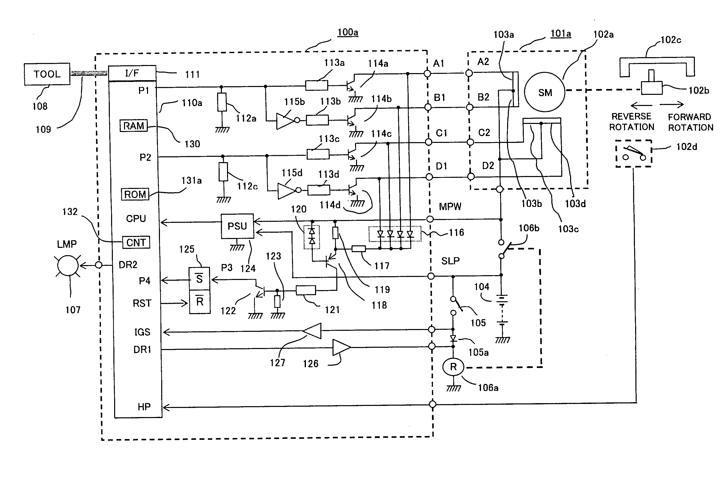
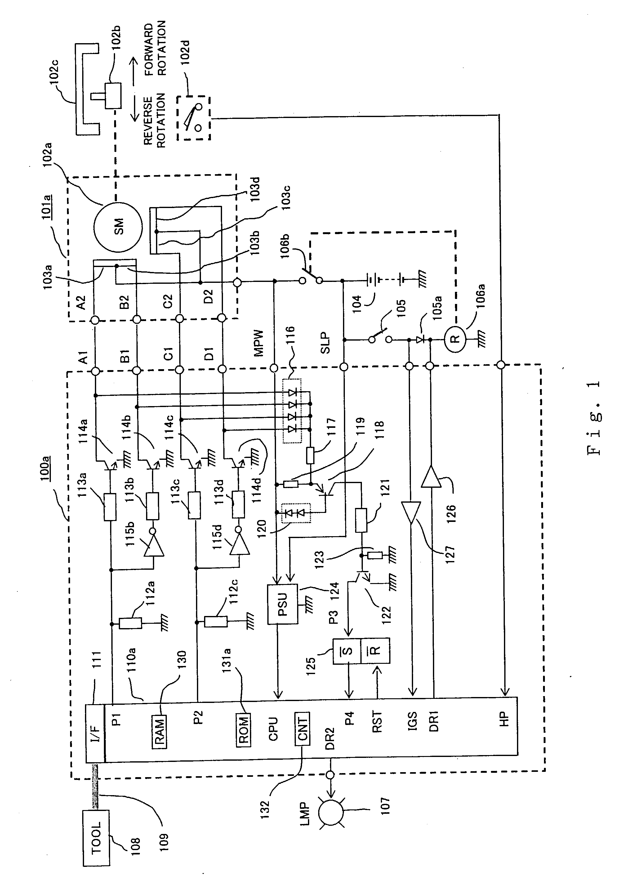
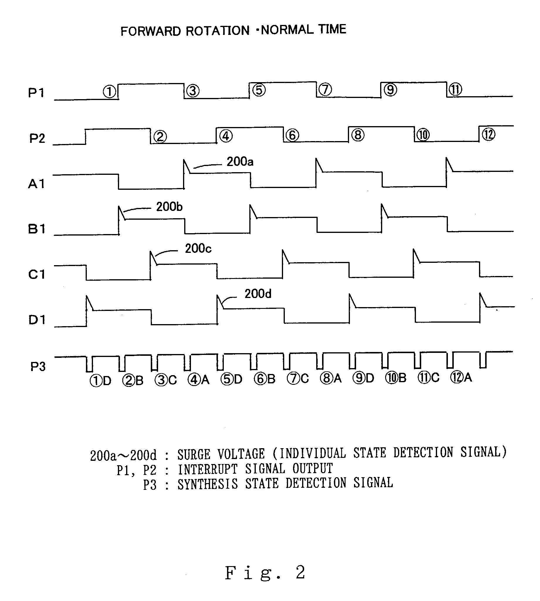
[0052] In the first embodiment according to the invention arranged as shown in FIG. 1, operation thereof is described first with reference to a time chart of the forward rotational operation of the stepping motor 101a shown in FIG. 2. Referring to FIG. 2, a rising edge of the interrupt signal output P1 from the microprocessor 110a is indicated by numerals {circle over (1)}{circle over (5)}{circle over (9)}, and a falling edge thereof is indicated by numerals {circle over (3)}{circle over (7)}{circle over (11)}. Further, a rising edge of the interrupt signal output P2 from the microprocessor 101a is indicated by numerals {circle over (4)}{circle over (8)}{circle over (12)}, and a falling edge thereof is indicated by numerals {circle over (2)}{circle over (6)}{circle over (10)}. At a point of the rising edge {circle over (1)}{circle over (5)}{circle over (9)} of the interrupt signal output P1, the interrupt signal output P2 is kept at a level of "H": while at a point of the falling ed...

embodiment 2

[0091]

[0092] b 1. Detailed Description of Constitution according to Embodiment 2

[0093] FIG. 7 is a block diagram showing another embodiment according to the invention. Differences from the first embodiment of FIG. 1 are primarily described below. With reference to FIG. 7, numeral 100b designates an abnormality detector that contains therein a microprocessor 110b, and controls driving a stepping motor 101b connected outside. Numeral 102a designates a rotor of the mentioned stepping motor 101b. In this second embodiment, the return-detecting switch 102d shown in FIG. 1 is not provided. Moreover, the power supply relay 106a shown in FIG. 1 is not used, and the abnormality detector 100b is directly power-fed from the on-vehicle battery 104, or fed via the power supply switch 105.

[0094] As for the internal constitution of the abnormality detector 114b, the collector terminals of the open / close elements 114a, 114b, 114c, 114d are connected to the connector terminals A1, B1, C1, D1 and dri...


PUM


Abstract

An abnormality detector for motor drive system easily detects, using a CPU, abnormality such as short circuit or disconnection in magnetic field coils of a motor, wiring, an open / close element, etc., which are controlled by a microprocessor (CPU). The open / close elements conducting an open / close operation sequentially in response to pulse outputs P1, P2 generated by the CPU, drive the magnetic field coils. Surge voltages generated upon interrupting the mentioned open / close elements are OR connected through a diode, and input to a temporary storage circuit. Then the CPU reads out, stores and resets the surge voltages using pulse edges of the pulse output P1 or P2. When any generation of the surge voltage is not stored in the temporary storage circuit, the CPU operates an abnormality alarm display.

Description

[0001] 1. Field of the Invention[0002] The present invention relates to an abnormality detector for detecting an abnormality of a motor drive system for use in a drive control, e.g., of a regulating valve of a circulation gas amount or an idle engine speed controlling intake valve, which are mounted in an exhaust gas circulation path of an automobile engine. More particularly, the invention relates to an improved abnormality detector for detecting an abnormality of a motor drive system by which it is easy to detect an abnormality such as disconnection, short circuit or the like in multiphase magnetic field coils themselves, driving open / close elements of the magnetic field coils, wiring between the magnetic field coils and the open / close elements or the like used in the motor drive system.[0003] 2. Description of the Related Art[0004] As means for detecting an abnormality such as disconnection, short circuit or the like at a load itself, a driving open / close element, wiring between ...

Claims


Application Information

Patent Timeline
Patent Type & Authority Applications(United States)
IPC IPC(8): F02D21/08H02H7/08F02D31/00F02D41/20F02D41/22F02D41/24H02P8/00H02P8/20H02P8/38
CPCF02D31/005F02D41/0065F02D41/20F02D41/221Y02T10/40F02D2041/2027F02D2041/2058F02D2041/2089F02D41/2432
Inventor NAKAMICHI, MASAKIHASHIMOTO, KOHJI
Owner MITSUBISHI ELECTRIC CORP
Why Eureka
Try Eureka