System for the transmission of audiovisual signals between source nodes and destination nodes

a technology of audiovisual signals and transmission systems, applied in the field of home audiovisual networks, can solve the problems of not being able to consider equipping each node of the network with such means, being unable to provide optimum protection of audiovisual signals at an acceptable cost, and two known protection mechanisms described here above (dctp and macrovision) cannot be used alone or in combination to provide optimal protection of audiovisual signals. at an acceptable cos

Inactive Publication Date: 2003-11-27
CANON EURPOPA NV
View PDF7 Cites 44 Cited by
  • Summary
  • Abstract
  • Description
  • Claims
  • Application Information

AI Technical Summary

Problems solved by technology

Now DTCP format encoding or decoding means are very costly at present.
It is therefore not possible to consider equipping each node of the network with such means.
It can be seen therefore that the two known protection mechanisms described here above (DCTP and "Macrovision") cannot be used alone or in combination to provide optimum protection to audiovisual signals at an acceptable cost.

Method used


Image

  • System for the transmission of audiovisual signals between source nodes and destination nodes
  • System for the transmission of audiovisual signals between source nodes and destination nodes
  • System for the transmission of audiovisual signals between source nodes and destination nodes

Examples


first embodiment

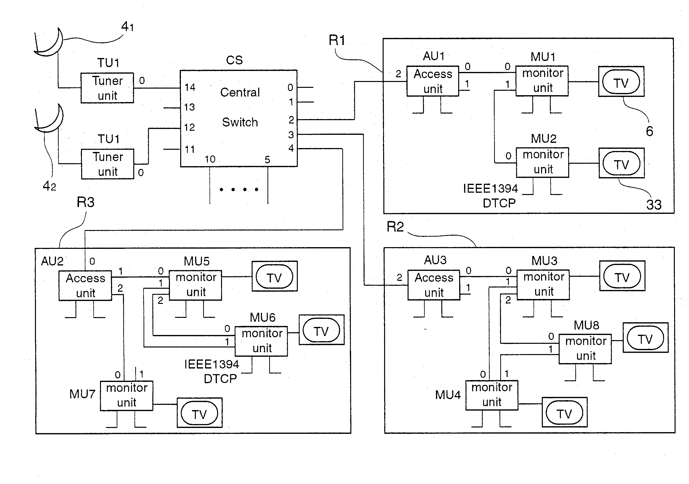
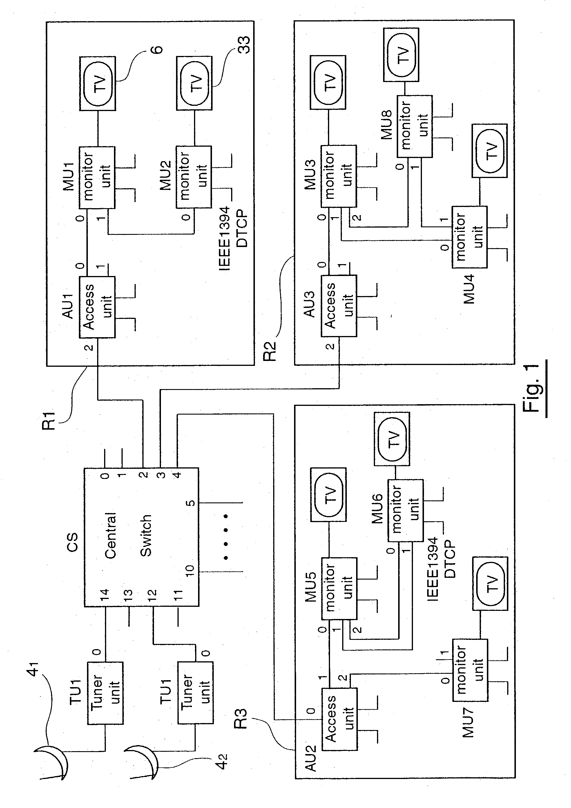
[0209] In a first embodiment, the interconnection management means comprise two sets of input / output ports. One contains input / output ports dedicated to the connection of the tuner units TU1, TU2. The other contains input / output ports dedicated to the connection of the access units AU1 to AU3. In this case, a switching matrix of the central switch CS is predefined as a function of the pre-determined assignments of the input / output ports.

second embodiment

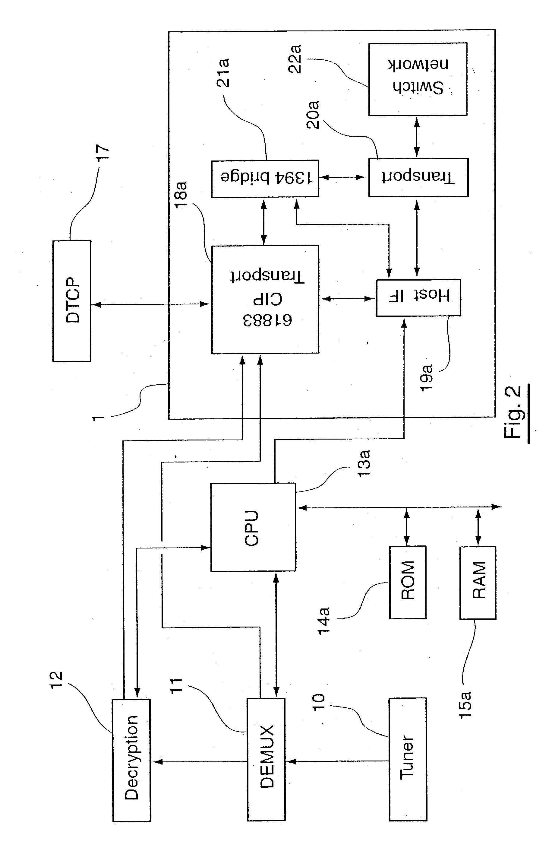
[0210] In a second embodiment, the interconnection management means comprise means for the management of an administration interface. This interface, whose program is executed by the central processing unit (CPU) 13d, enables an administrator of the system to define switching parameters within the central switch CS. In other words, the administrator defines the paths authorized inside the central switch CS, then programs the switching matrix of the central switch CS.

third embodiment

[0211] In a third embodiment, the interconnection management means comprise means for the dynamic identification of the access units AU1 to AU3 and the tuner units TU1, TU2 connected to the central switch CS. This dynamic identification is, for example, based on identifiers or keys specific to each of the access units and tuner units. The central switch CS asks for the identifiers of the nodes that are connected to it and automatically defines the switching matrix. Furthermore, in this case, if the central switch CS detects an unauthorized junction (or loop) between two home audiovisual networks, it may invalidate the data paths, in the switching matrix, from the source nodes to these home audiovisual networks. These paths will not be validated again until after the disappearance of the unauthorized loop.

[0212] FIG. 6 illustrates a topological map of the system of FIG. 1, forming a total switched network. The map is stored in the RAM of each node. It may be updated on each node, esp...


PUM


Abstract

A system for the transmission of audiovisual signals between at least one source node and at least one destination node comprises: at least one central switch to which at least one source node is connected and at least two home audiovisual networks, each comprising a plurality of nodes each capable of playing the role of a destination node to which said audiovisual signals are transmitted from said at least one source node. Each home audiovisual network is connected to said at least one central switch by means of said at least one of its nodes. Said at least one central switch comprises interconnection management means. These means themselves comprise means for the selective authorisation of a first type of transmission of audiovisual signals through said at least one central switch from said at least one source node to at least one of the destination nodes of one of the home audiovisual networks.

Description

[0001] 1. Field of the Invention[0002] The field of the invention is that of home audiovisual networks of the type used to interconnect a plurality of audio and / or video analog and / or digital type terminals (also called devices) so that they exchange audiovisual signals.[0003] These terminals belong, for example, to the following list of equipment (which is not exhaustive): television receivers (using satellite, RF channels, cable, xDSL and other means), television sets, video tape recorders, scanners, digital video cameras, digital cameras, DVD readers, computers, personal digital assistants (PDAs), printers, etc.[0004] The home audiovisual networks are, for example, of the high-bit-rate switched type comprising a small number of nodes, used especially for the real-time exchange of moving pictures for distribution within a dwelling.[0005] The home audiovisual networks according to the invention comprise a plurality of nodes connected by a plurality of physical communication links. ...

Claims


Application Information

Patent Timeline
Patent Type & Authority Applications(United States)
IPC IPC(8): H04N7/10H04N7/169H04N7/173
CPCH04N7/106H04N7/1693H04N21/4627H04N21/43615H04N21/43632H04N7/17318
Inventor BIZET, STEPHANE
Owner CANON EURPOPA NV
Why Eureka
Try Eureka