Wrist & headband with a source of cooling energy

a technology of cooling energy and wrist and headband, which is applied in the field of wrist & headband with a source of cooling energy, can solve the problems of affecting user performance, presenting health risks, and not being particularly effective in a particular technique, and achieves the effect of facilitating the use of a relatively non-stretchable fabric and facilitating stretching

Inactive Publication Date: 2003-12-04
RIVERA ROBERT +1
View PDF5 Cites 40 Cited by
  • Summary
  • Abstract
  • Description
  • Claims
  • Application Information

AI Technical Summary

Benefits of technology

0018] In an alternative embodiment the device of this invention, the structural component of the device are comparatively inelastic. In order to accommodate the placement and removal thereof from the anatomy of the wearer, the inelastic band includes an elastic strip, or insert, running across the width of the device. This strip or insert is expandable and connects the inelastic portions of the band together to complete the assembly band and facilitate stretching thereof. The flexible strip or insert is prefera

Problems solved by technology

However, this technique is not particularly effective when the humidity is high.
Other techniques, such as drinking cold liquids, may affect the user's performance and possibly present health risks.
No effective means of providing a cooled band for use in sports is presently known.
Additionally, no means is presently known for maintaining contact of a therapeutic cold pack with an anatomical portion of a user's body during sports activities.
As such, although the prior art has recognized to a limited extent the problems of absorbing perspiration during sporting events and of cooling the participants, the proposed solutions have to date be

Method used


Image

  • Wrist & headband with a source of cooling energy
  • Wrist & headband with a source of cooling energy
  • Wrist & headband with a source of cooling energy

Examples


Embodiment Construction

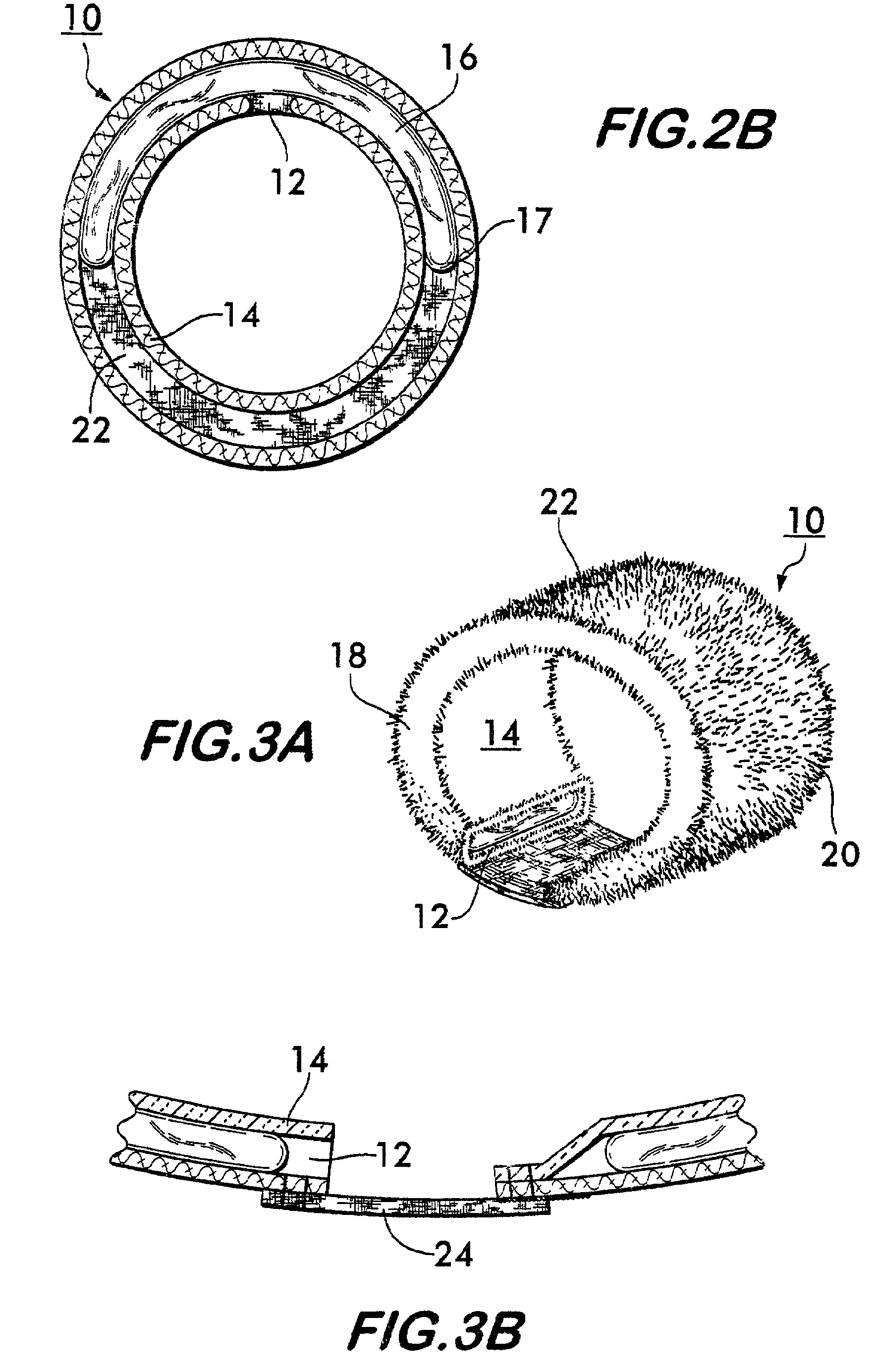
[0022] The Figures which accompany this application, and referenced herein, depict a representative embodiment of the wrist and headband of this invention. In the embodiments of this invention illustrated in these Figures, one or more components of the wrist and head band may appear in more than one Figure. Accordingly, components which are common to more than one Figure are assigned a common reference numeral for continuity of description and ease of understanding.

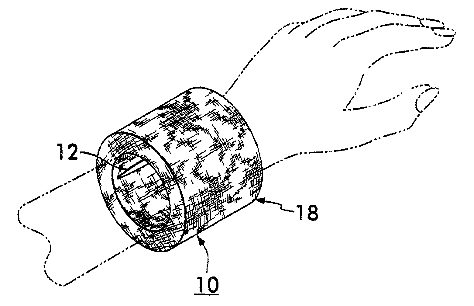
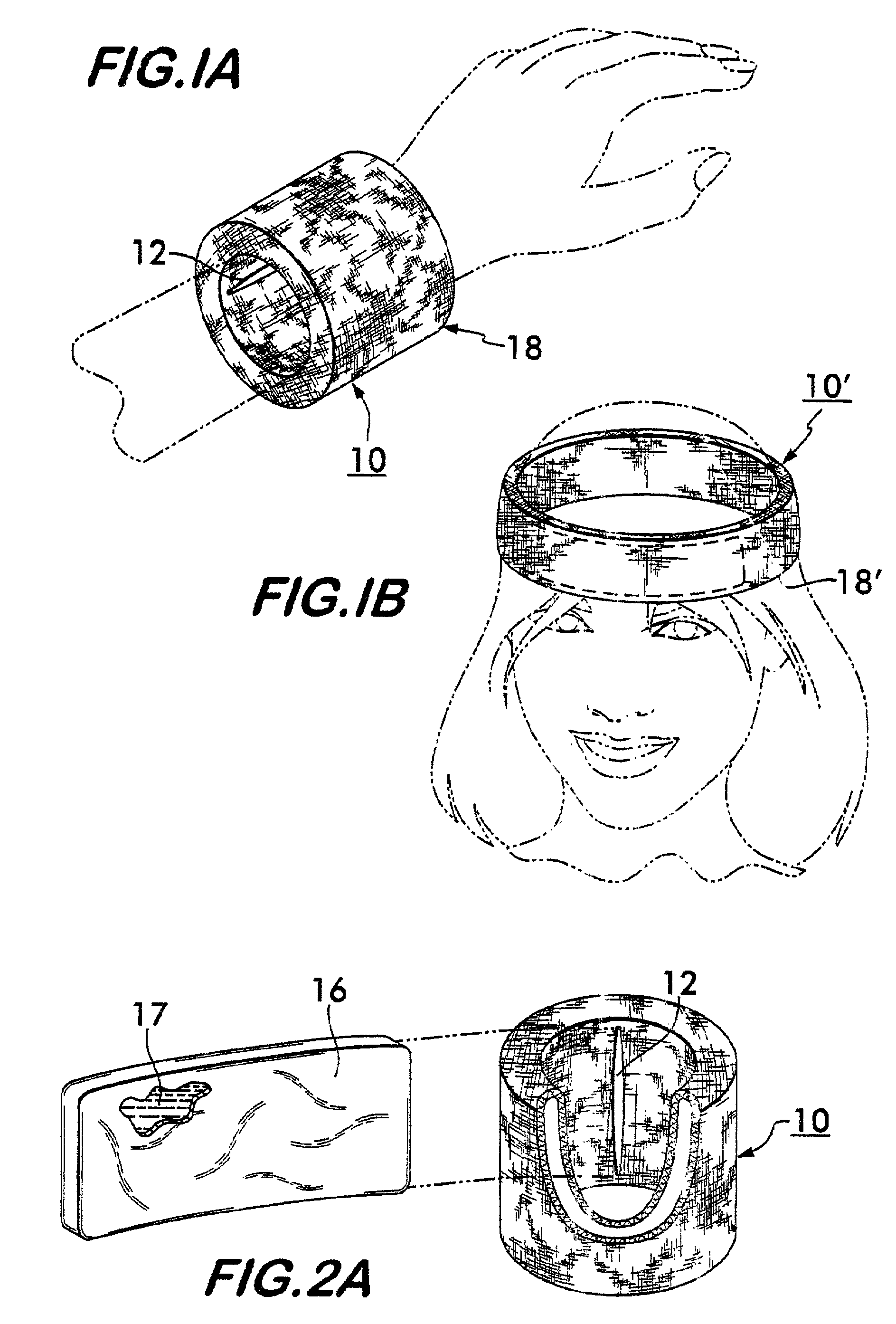
[0023] FIG. 1 depicts an anatomically fitted sleeve or band positioned on a wearer's wrist (wrist band (10)) and on a wearer's head (headband (10')). In each instance, the anatomically fitted sleeve (10) or band (10') comprises a thermally insulating elastomeric material comprising a closed cell foam. The materials used in the fabrication of this anatomically fitted sleeve (10) or band (10') is of sufficient thickness to thermally insulate the skin of the wearer from the ambient environment. This anatomically fitted sleev...


PUM


Abstract

The wrist or headband described herein is of composite construction, specifically, an essentially continuous elastic band or sleeve, which is anatomically conforming in overall dimensions to the approximate wrist or headband size of a wearer; and, a moisture absorbent material, associated with at least one end of the sleeve, to wick moisture from the interface of a wearer and the sleeve into a reservoir located on the exterior surface of the sleeve. The sleeve is preferably fabricated of the same material as the foam fabric used in the fabrication of a SCUBA diver's suit, specifically, a closed cell foam. The thickness of such materials is generally uniform throughout the device and designed to provide more than adequate thermal insulation for the source of cooling energy housed within the device. The sleeve is further modified on the interior surface thereof (also "skin contact surface") to accommodate a source of thermal energy (also "chill pack"). This modification of the interior of the sleeve (also herein "chill pocket") can include a compartment for containment of a source of cooling thermal energy, or integral bladder containing a high heat capacity fluid or gel.

Description

[0001] 1. Field of the Invention[0002] This invention relates to an article of manufacture. More specifically, this invention is directed to device which includes an anatomically fitted sleeve (10) or band (10') having a source of cooling energy associated therewith, and means, distinct from the source of cooling energy, for absorbing perspiration. The device is designed for use in an active environment while maintaining itself in position on the body during work or play.[0003] 2. Background of Invention[0004] Headband s and wrist band s worn during sports, such as tennis and volleyball, are well known. Such bands are commonly worn to absorb perspiration, thereby preventing perspiration from contacting the user's eyes and / or hands where it may potentially interfere with the user's performance. Such contemporary bands typically comprise elastic terry cloth or the like which is configured to snugly encircle the wearer's wrist or the upper portion of the user's head.[0005] Flexible col...

Claims


Application Information

Patent Timeline
IPC IPC(8): A41D20/00
CPCA41D20/005
Inventor RIVERA, ROBERTELIAS, VICTOR A.
Owner RIVERA ROBERT
Why Eureka
Try Eureka