

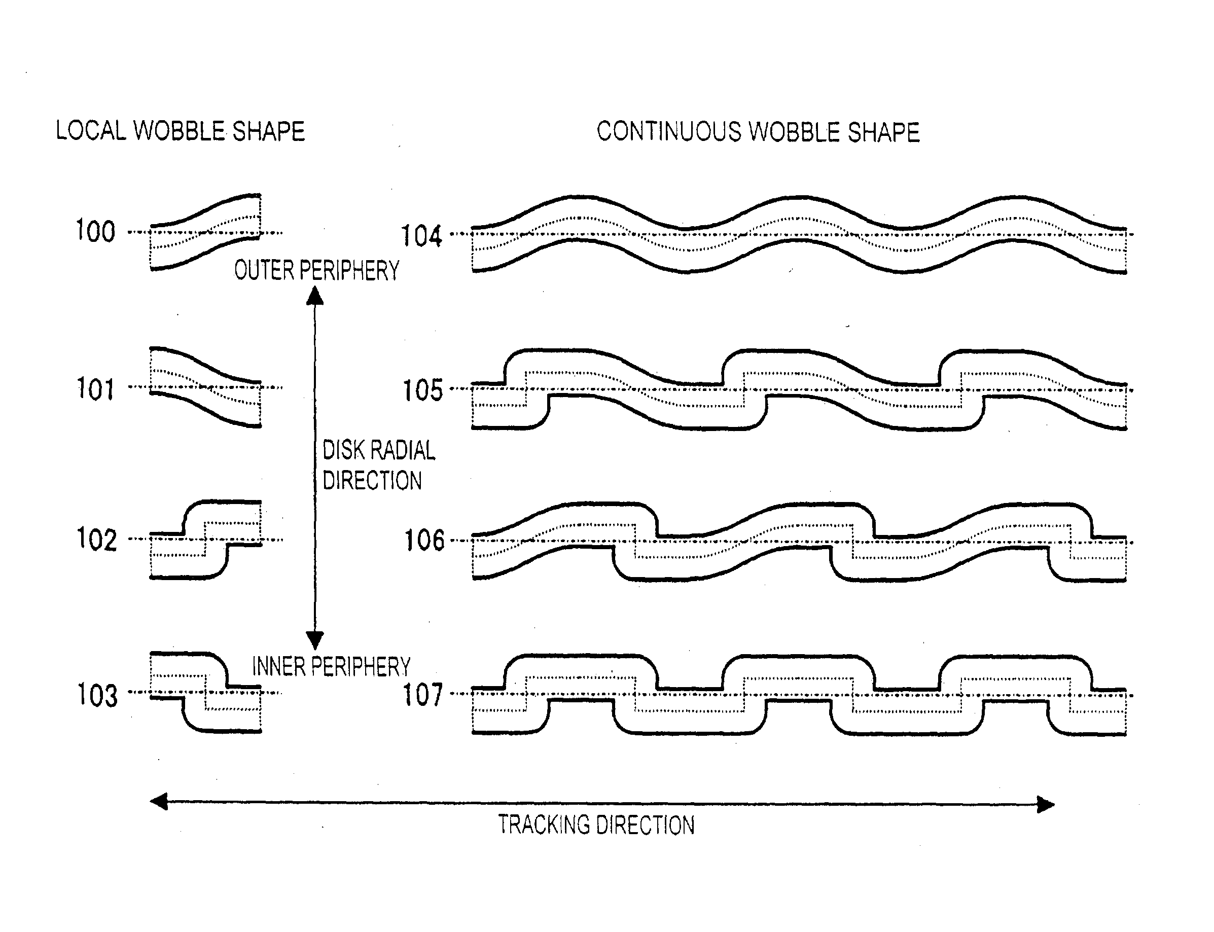
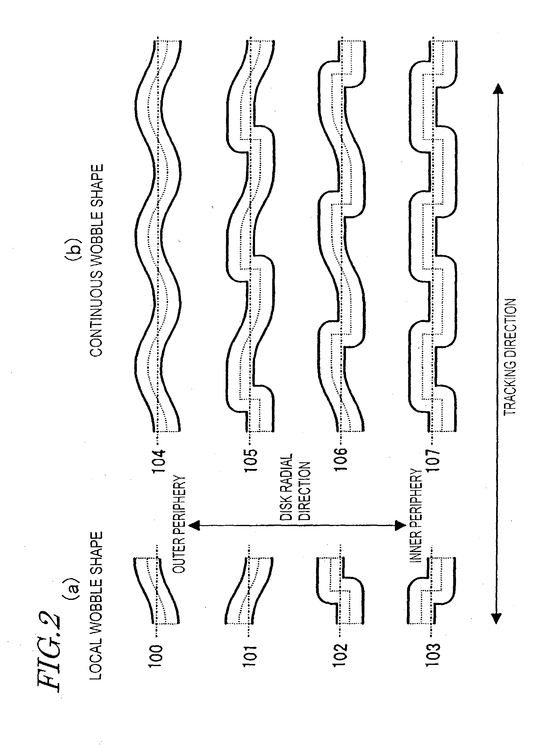
Optical disk having wobble patterns representing control information
a control information and optical disk technology, applied in the field of optical disks, can solve the problems of jitter in the resultant recording signal, reduced storage capacity available for users, and inability to sufficiently follow up the jitter of the disk motor or the jitter,
- Summary
- Abstract
- Description
- Claims
- Application Information
AI Technical Summary
Problems solved by technology
Method used
Image

Examples
embodiment 2
[0169] Hereinafter, an optical disk apparatus (disk drive) having the function of reading an address on the optical disk medium of the first embodiment will be described with reference to FIG. 5.
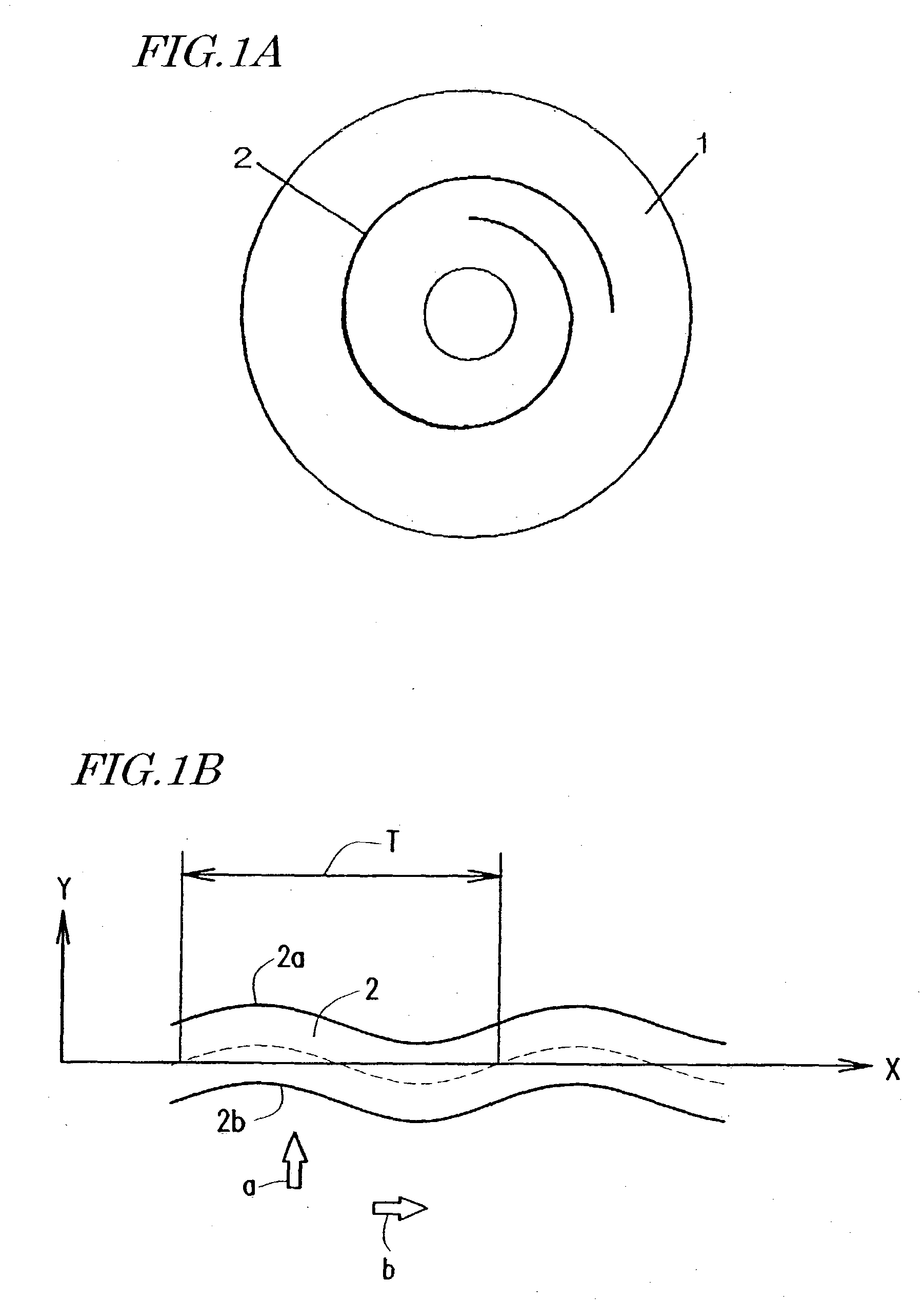
[0170] A laser beam, emitted from the optical head 331 of this apparatus, impinges onto an optical disk 1, thereby forming a light spot on the track groove of the optical disk 1. A drive mechanism is controlled in such a manner that the light spot moves on the track groove as the optical disk 1 is rotated.
[0171] The optical head 331 then receives the laser beam that has been reflected by the optical disk 1, thereby generating an electric signal. The electric signal is output from the optical head 331 and then input to a read signal processor 332 where the electric signal is subjected to operation processing. In response to the signal supplied from the optical head 331, the read signal processor 332 generates and outputs a fully added signal and a wobble signal (i.e., push-pull signal).
[0172]...
embodiment 3
[0180] Another embodiment of the optical disk apparatus of the present invention will be described with reference to FIG. 6. The optical disk apparatus of this embodiment is different from the apparatus according to the fourth embodiment in that the apparatus further includes an erasure detector 340. The error corrector 339 also has a different function. In the other respects, the apparatus of this embodiment is the same as the counterpart of the second embodiment. Thus, the description of the components commonly used for these two embodiments will be omitted herein.
[0181] The erasure detector 340 compares the count C1 output from the first shape counter 336 with the count C2 output from the second shape counter 337 for each unit section. And when an inequality -E<C1-C2<+E is satisfied with respect to a predetermined value E, the detector 340 outputs an erasure flag of "1" indicating that the subdivided information is not definitely identifiable. On the other hand, if the inequality...
embodiment 4
[0186] An inventive method for reading an address on an optical disk medium will be described with reference to FIG. 7.
[0187] A wobble shape 351 is schematically illustrated on the upper part of FIG. 7. In the left half of the wobble shape 351, falling displacements are steep. In the right half thereof on the other hand, rising displacements are steep.
[0188] The wobble signal 352 as represented by a push-pull signal has had its quality deteriorated by noise or waveform distortion.
[0189] A digitized signal 353 is obtained by slicing the wobble signal 352 at zero level. A differentiated signal 354 is obtained by differentiating the wobble signal 352. The differentiated signal 354 contains information about the gradients of the wobble shape. A number of peaks reflecting noise or waveform distortion are observed here and there in addition to those peaks representing the gradients detected for displacement points.
[0190] For the sake of simplicity, only first and second parts 355 and 356 ...
PUM
 Abstract
Description
Claims
Application Information