Oil-cooled compressor

a compressor body and oil-cooled technology, applied in the direction of machines/engines, liquid fuel engines, positive displacement liquid engines, etc., can solve the problems of complicated structure and inconvenient operation of the compressor body

Active Publication Date: 2003-12-04
KOBELCO COMPRESSORS CORP
View PDF6 Cites 17 Cited by
  • Summary
  • Abstract
  • Description
  • Claims
  • Application Information

AI Technical Summary

Problems solved by technology

As to a more increase of temperature, there can be a case where the temperature rises up to near the upper-limit discharge temperature T.sub.dmax or may exceed the upper-limit discharge temperature, which would cause inconvenience in the operation of the compressor body.
However, the compressor in the prior document has a complicated structure which additionally includes a discharge temperature sensor and an oil control valve changing supply oil quantity continuously.
In addition, though it is assumed that a complicated control algorithm should be applied for thus complicated structure, the prior document discloses nothing about the control algorithm.

Method used


Image

  • Oil-cooled compressor
  • Oil-cooled compressor
  • Oil-cooled compressor

Examples


Embodiment Construction

[0027] An example in which the oil-cooled compressor according to an embodiment of the present invention is an oil-cooled screw compressor will be described hereinunder with reference to drawings attached hereto.

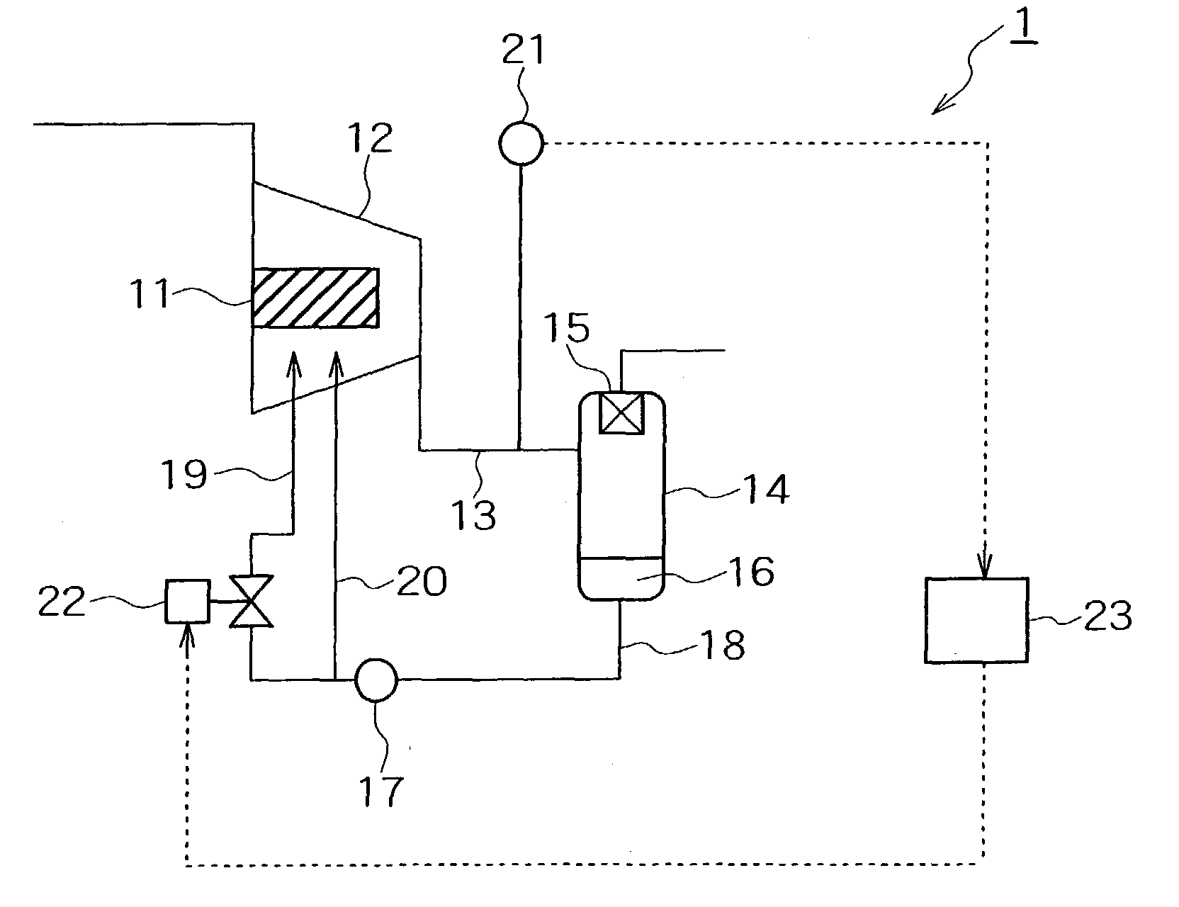
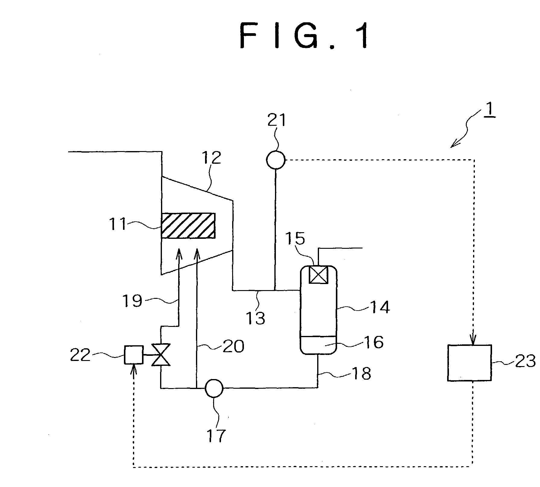
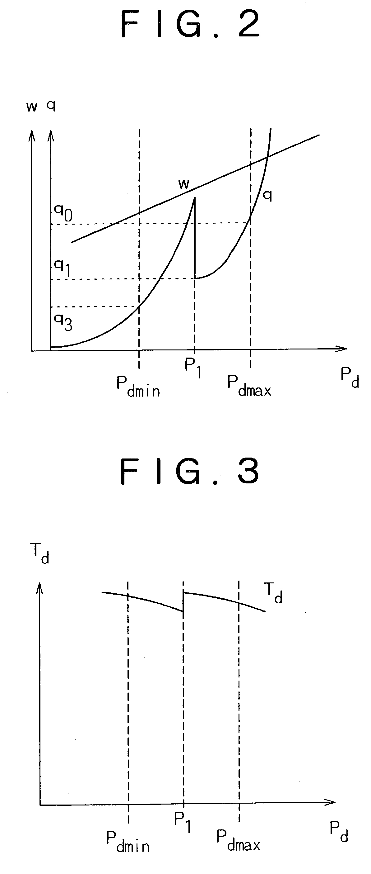
[0028] FIG. 1 is a schematic system diagram of an oil-cooled screw compressor, FIG. 2 is a graph explaining a relation between a discharge pressure P.sub.d and power w of a compressor body and a relation between the discharge pressure P.sub.d and an oil quantity q, and FIG. 3 is a graph explaining a relation between the discharge pressure P.sub.d and a discharge temperature T.sub.d. As to portions common to the conventional oil-cooled screw compressor described above in connection with FIG. 4, they are identified by the same reference numerals as those in FIG. 4 and a description will be given of different points.

[0029] First, with reference to FIG. 1, an oil-cooled screw compressor 1 according to an embodiment of the present invention will be described. In the oil-cooled sc...


PUM


Abstract

An oil-cooled screw compressor which can maintain the discharge temperature of discharge gas at an appropriate level is provided. The oil-cooled screw compressor comprises a compressor body, an oil separation/recovery unit disposed in a discharge path extending from a discharge port of the compressor body, and an oil feed path extending from the oil separation/recovery unit and communicating with the compressor body 12. The oil feed path is branched at an intermediate position thereof into a first feed path portion and a second feed path portion. An opening/closing valve is disposed in the first feed path portion, a pressure gauge is disposed in the discharge path, and a control unit is provided to control opening and closing of the opening/closing valve on the basis of a correlation between a discharge pressure detected by the pressure gauge and a predetermined pressure.

Description

[0001] 1. Technical Field of the Invention[0002] The present invention relates to an oil-cooled compressor which is constructed so that oil is fed to a body of the compressor for lubrication, cooling, or shaft sealing. Particularly, the invention is concerned with an oil-cooled compressor in which the discharge temperature of discharge gas is controlled appropriately by controlling the amount of oil to be fed.[0003] 2. Description of the Related Art[0004] There is known an oil-cooled compressor constructed such that oil is fed to a body of the compressor for lubrication, cooling, or shaft sealing. An example in which this known oil-cooled compressor is an oil-cooled screw compressor will now be described with reference to drawings attached hereto. FIG. 4 is a schematic system diagram of an oil-cooled screw compressor, FIG. 5 is a graph explaining a relation between a discharge pressure P.sub.d and a power w of a compressor body and a relation between the discharge pressure P.sub.d a...

Claims


Application Information

Patent Timeline
Patent Type & Authority Applications(United States)
IPC IPC(8): F04B39/02F04B39/12F04B39/06F04C29/00F04C29/02
CPCF04C29/042F04C29/0014
Inventor NAKAMURA, HAJIMETOTSUKA, JUNICHIROYOSHIMURA, SHOJI
Owner KOBELCO COMPRESSORS CORP
Why Eureka
Try Eureka