Pneumatic projectile launching apparatus with partition-loading apparatus

a technology of pneumatic projectile and launching apparatus, which is applied in the direction of compressed gas guns, weapons, white arms/cold weapons, etc., can solve the problems of bolt and hammer having a large amount of reciprocating mass, affecting accuracy, and bolt and hammer having no natural lifting or lowering geometry, so as to improve the consistency of the launching apparatus

Inactive Publication Date: 2003-12-11
REIBLE JAMES PATRICK
View PDF40 Cites 46 Cited by
  • Summary
  • Abstract
  • Description
  • Claims
  • Application Information

AI Technical Summary

Benefits of technology

0085] h.) Consistency of the launching apparatus is improved by using an opposed piston regulator that vents overpressure.
0086] A further advantage over prior art is the opposed-piston regulator design.

Problems solved by technology

There are several distinct disadvantages to these designs:
d.) the bolt and hammer have a great amount of reciprocating mass, the momentum of which inhibits accuracy.
The bolt has no natural lifting or lowering geometry and therefore, cuts, chops, or squashes the projectile.
One common problem occurs when the bolt moves forward before the pellet is entirely in the breech, and the bolt crushes the paintball.
Once the pellet is crushed, the shell and the gelatinous fill are squirted up into the feed conduit, possibly destroying other pellets, into the breech of the gun, and on the bolt itself, possibly impairing function of the gun.
The bolt-type mechanism can also lead to jamming the gun.
However, because they used a hand pump method to move the bolt, reset the hammer, and load pellets more slowly, the problem was not as acute.
The development of semi-automatic firing increased the rate of fire and augmented the problem of damaging pellets as they load.
These motions create a jerky movement before and during the firing cycle that greatly impairs the accuracy.
Prior art has failed to solve this problem because no design to date has effectively eliminated heavy moving parts and effectively employed an alternate means to load the projectiles and activate the exhaust cycle.
The sealing point of the regulator is inconsistent.
If gas within the regulator expands or exceeds the set pressure for any reason, the pressure of the gas will continue to move the output piston to a point where the piston leaves its seal and vents overpressure until pressure normalizes and the piston returns to its seal, thus creating a failsafe mechanism.

Method used


Image

  • Pneumatic projectile launching apparatus with partition-loading apparatus
  • Pneumatic projectile launching apparatus with partition-loading apparatus
  • Pneumatic projectile launching apparatus with partition-loading apparatus

Examples


Embodiment Construction

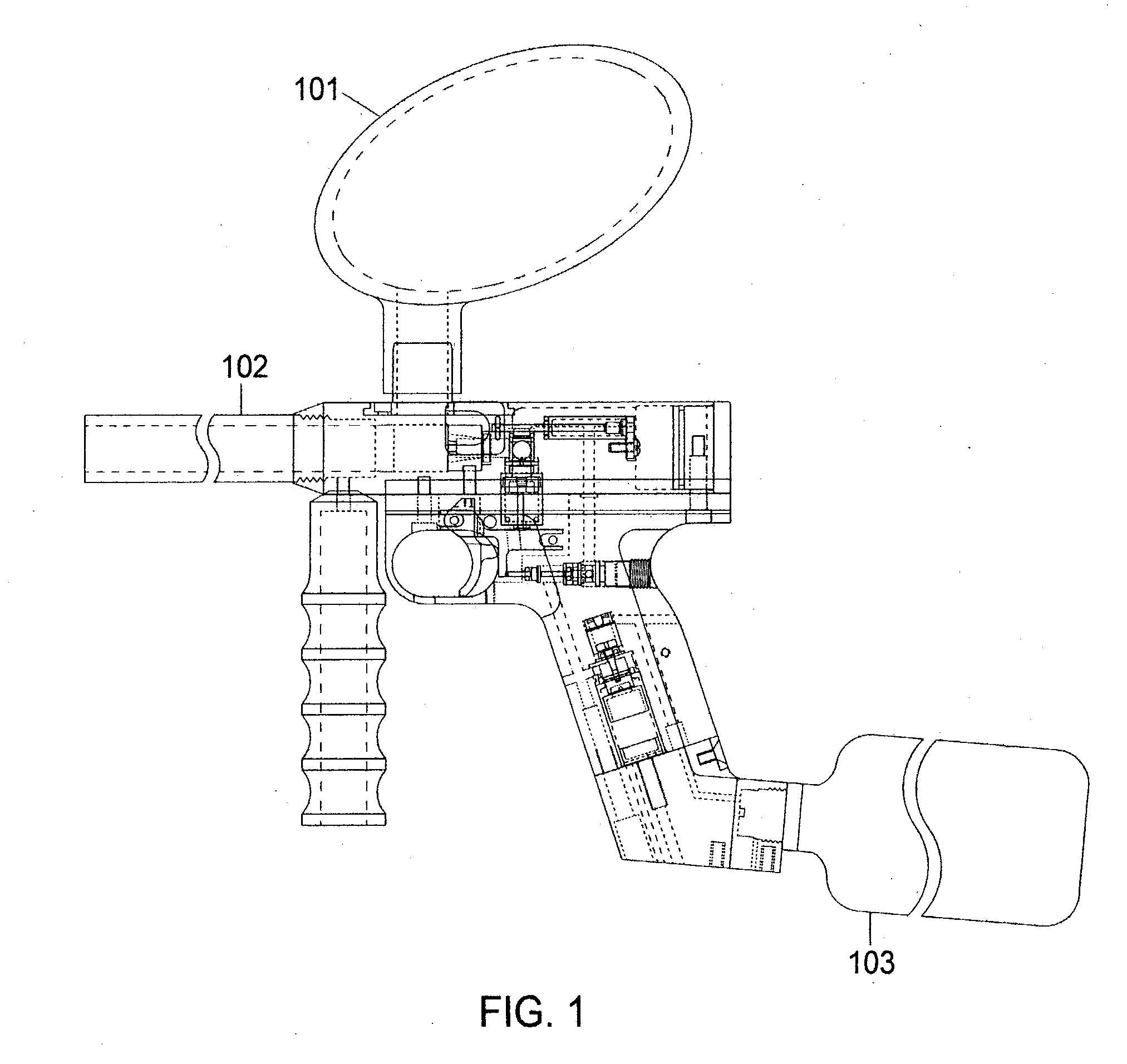
[0092] FIG. 1 illustrates a projectile launching apparatus according to a preferred embodiment of the present invention which is compressed gas powered semi-automatic action apparatus capable of expelling projectiles of like size out of an attached barrel 102. The common use of this apparatus is as a marker or gun to propel gelatinous capsules known as paintballs; however, the projectiles should not be limited to this specific application. A projectile-storage chamber 101, such as a paintball loader, is preferably attached to a feed conduit 202. A compressed gas source 103 is preferably attached to a gas system adapter 235 by means of the threaded cavity 342 to provide a power source to operate the apparatus and propel the projectile.

[0093] A gas system adapter 235 attaches to the bottom of a grip frame 220 and directs inlet gas to flow from an external gas source 103 through a filter 233 located in the grip frame 220. A passage 330 extends past the filter 233 and directs the gas in...


PUM


Abstract

An improved pneumatic launching apparatus is disclosed having both a partition apparatus for enabling a projectile, such as filled capsules used in paintball, marking devices or crowd control, to be loaded and readied for expulsion and a venting-pressure regulator. When the partition apparatus is in an open position, an aperture is exposed allowing a projectile of complimentary size and shape to transfer to the receiving chamber. The shape of the partition is such that a next projectile is gently cradled and separated from the receiving chamber during a closing movement. Further, the partition facilitates the projectile reaching a containing area and it creates a seal that on the chamber that significantly inhibits the escape of pressurized gas during a firing operation and facilitates the projectile loading into a containing area. The venting-pressure regulator utilizes opposed pistons with an escape mechanism to allow venting to occur without requiring a separate adjustment.

Description

[0001] This is a continuation-in-part of patent application Ser. No. 10 / 067,228, filed Feb. 7, 2002. I hereby claim the benefit under Title 35, United States, .sctn.120 of the prior, co-pending United States application listed below and, insofar as the subject matter of each of the claims of this application is not disclosed in the manner provided by the first paragraph of Title 35, United States Code .sctn.112, I acknowledge the duty to disclose material information as defined in Title 37, Code of Federal Regulations, .sctn.1.56(a), which occurred between the filing date of this application and the national or PCT international filing date of this application Ser. No. 10 / 067,228, filed Feb. 7, 2002.[0002] 1. Field of the Invention[0003] This invention relates to compressed gas powered guns or projectile launching apparatuses that propel projectiles, and more specifically to an improved method for loading and propelling projectiles.[0004] 2. Description of Prior Art[0005] Numerous t...

Claims


Application Information

Patent Timeline
Patent Type & Authority Applications(United States)
IPC IPC(8): F41B11/02F41B11/32
CPCF41B11/52F41B11/723F41B11/724F41B11/57
Inventor REIBLE, JAMES PATRICK
Owner REIBLE JAMES PATRICK
Why Eureka
Try Eureka