High-pressure fuel injection pipe having connecting head portion

Inactive Publication Date: 2003-12-18
USUI KOKUSAI SANGYO KAISHA LTD
View PDF17 Cites 19 Cited by
  • Summary
  • Abstract
  • Description
  • Claims
  • Application Information

AI Technical Summary

Problems solved by technology

However, such a prior art high-pressure fuel injection pipe having a connecting head portion has a problem of causing during a practical use of the injection pipe the cavitation erosion of a part thereof around a deep, sharp and large annular pocket, which is formed in an inner surface of a connecting head portion, to occur during a practical use thereof due to a high-pressure fluid, and a problem of having the possibility that a fatigue failure of the fuel injection pipe starts at the deepest part of the

Method used


Image

  • High-pressure fuel injection pipe having connecting head portion
  • High-pressure fuel injection pipe having connecting head portion
  • High-pressure fuel injection pipe having connecting head portion

Examples


Embodiment Construction

:

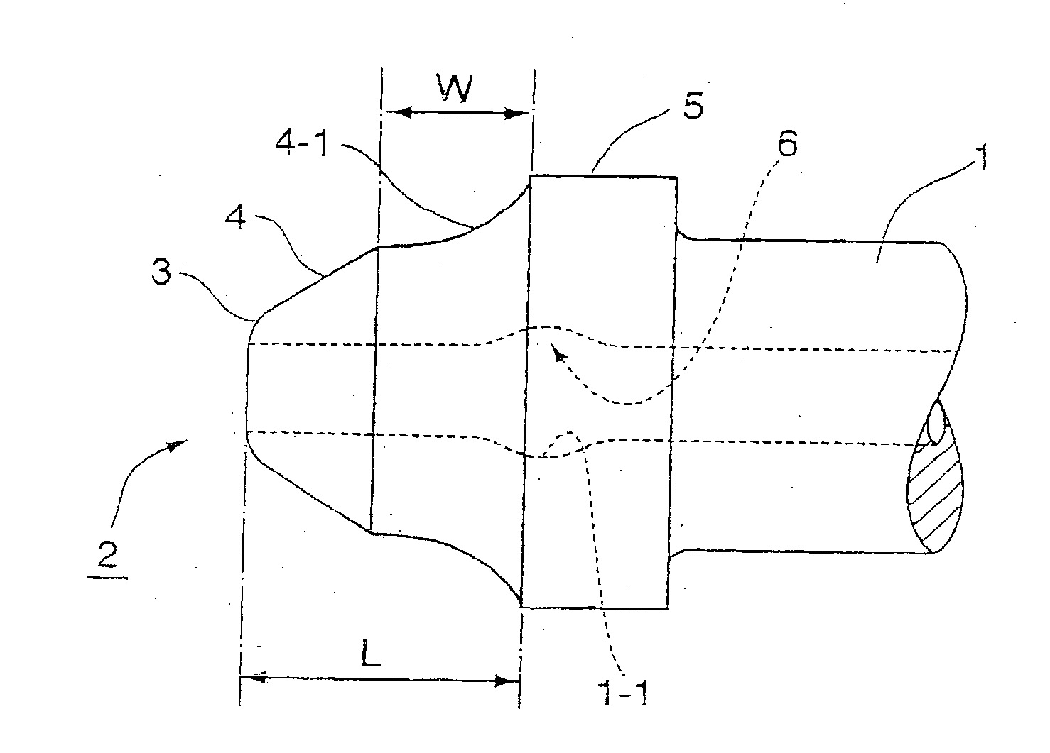
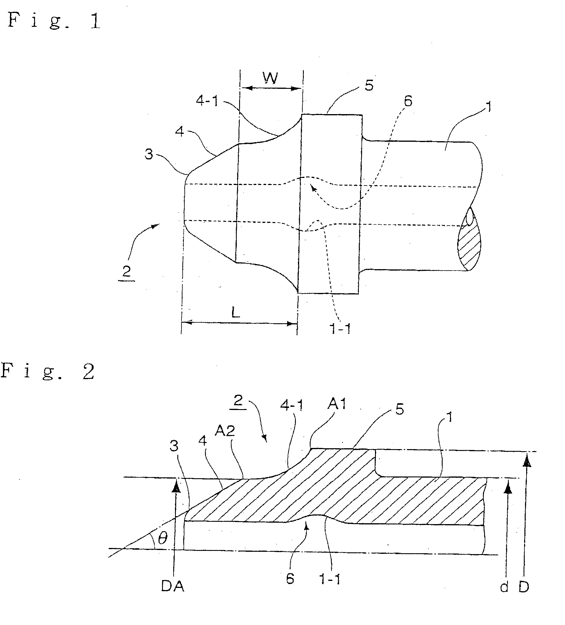
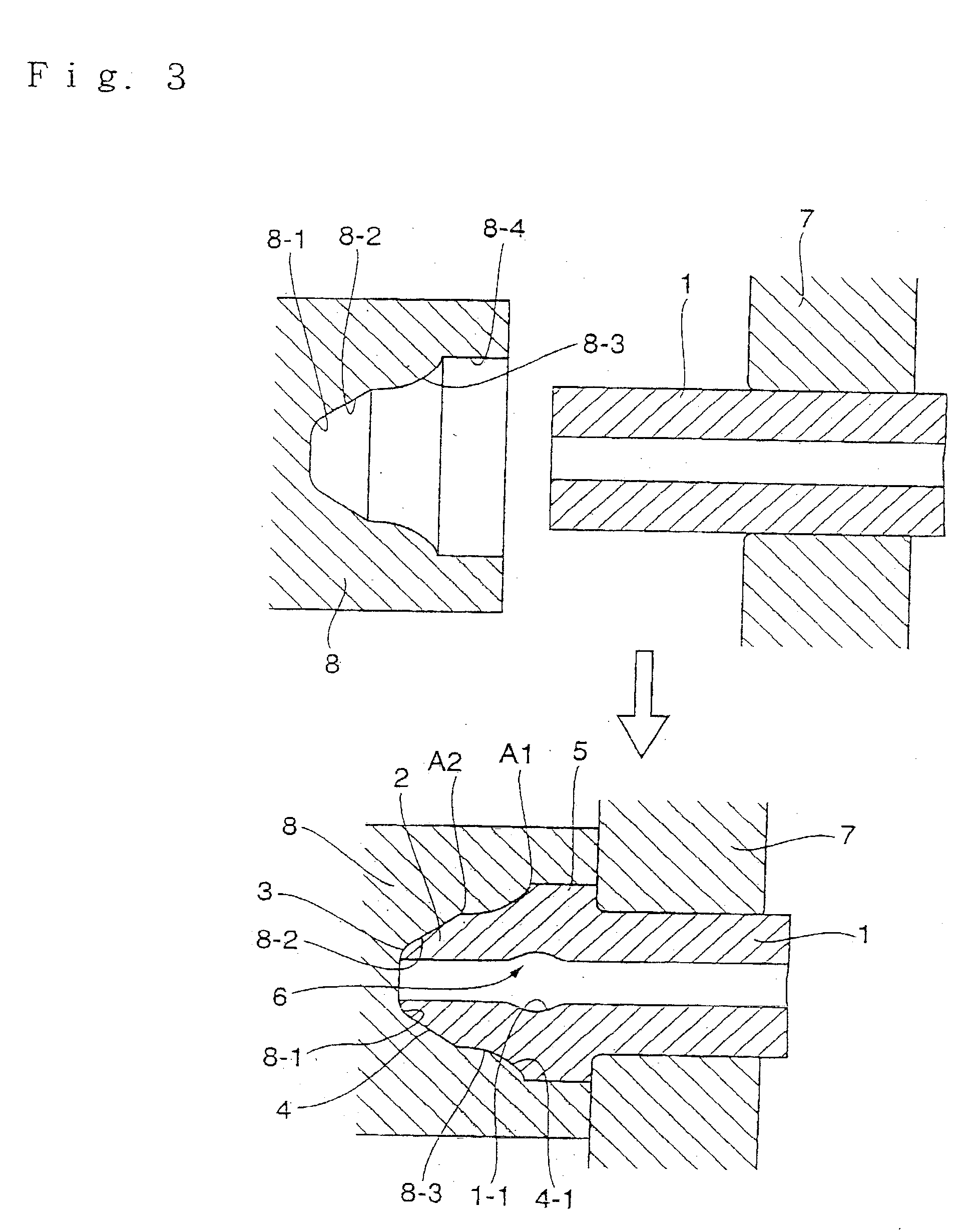
[0017] According to the present invention, a reference numeral 1 denotes a thick-walled steel pipe having relatively small diameter, 2 a connecting head portion, 3 a seat surface, 4 a conical surface, 5 an annular flange, 6 a pocket, 1 a chuck, and 8 a punch member.

[0018] The thick-walled steel pipe 1 is a thick-walled pipe of a relatively small diameter of about 4 m / / m, to about 20 m / m and a wall thickness of about 1 m / m to about 8 m / m made of a carbon steel pipe used as a high-pressure pipe and cut off to a predetermined size beforehand.

[0019] A high-pressure fuel injection pipe shown in FIG. 1 and FIG. 2 has at a connecting end part of a thick-walled steal pipe 1 a connecting head portion 2 which includes a seat surface 3 formed on a connecting end portion of the thick-walled steel pipe 1 and engageable at an outer circumferential surface thereof with a seat portion of a punch, an annular flange 5 provided so that the flange is spaced axially from the sear surface 3, a conical s...


PUM

PropertyMeasurementUnit
Pressureaaaaaaaaaa
Diameteraaaaaaaaaa

Abstract

A high-pressure fuel injection pipe having connecting head portion is provided which is capable of eliminating a fear of the occurrence of cavitation erosion of the inner surface of the connecting head portion and a fatigue failure of the same head portion by having a contour of a cross section of an annular pocket occurring in an inner part of the connecting head portion during a head portion processing operation extend shallowly and gently. This fuel injection pipe has at a connecting end portion of a thick-walled steel pipe having a relatively small diameter, including a seat surface, an annular flange formed so that the flange is axially spaced from the seat surface, and a conical surface connected to the seat surface, extending therefrom to the annular flange and tapering off to a free end of the connecting head portion, wherein the conical surface is provided at a part thereof with an annular, shallow, cross-sectionally curved recess.

Description

[0001] 1. Field of the Invention[0002] This invention relates to a high-pressure fuel injection pipe having a connecting head portion at a free end thereof made of a thick-walled pipe having a relatively small diameter of about 4 m / m to about 20 m / m and a wall thickness of about 1 m / m to 8 m / m used widely in a suitably arranged state as a fuel supply path and the like for, for example, a diesel internal combustion engines.[0003] 2.Description of the Prior Art[0004] The known high-pressure fuel injection pipes of this kind include high-pressure fuel injection pipe having a connecting head portion (JP-A-8-75075) having as shown as an example in FIG. 4 at a connecting end portion of a thick-walled steel pipe 11 having a relatively small diameter a connecting head portion 12 formed with a seat surface 13, an annular flange 15 formed so that the flange 15 is axially spaced from the seat surface 13, and a conical surface 14 connected to the seat surface 13, extending therefrom to the annu...

Claims


Application Information

Patent Timeline
IPC IPC(8): F02M55/00F02M55/02F16L19/02F16L19/028
CPCF02M55/005F16L19/0283F02M55/02B21J5/08B21C37/06
Inventor FURUGEN, MUNEKATSUISHIDA, SHIGEYUKIKATO, NOBUO
Owner USUI KOKUSAI SANGYO KAISHA LTD
Why Eureka
Try Eureka