Eureka AIR delivers breakthrough ideas for toughest innovation challenges, trusted by R&D personnel around the world.

Optical touch panel and method for manufacturing the same

a touch panel and optical technology, applied in the field of optical touch panels, can solve the problems of difficult assembly and alignment, high cost, and inability to achieve achieve the effects of high optical transmission efficiency, high impact resistance, and easy assembly and alignmen

Inactive Publication Date: 2010-01-07
NITTO DENKO CORP
View PDF20 Cites 15 Cited by
  • Summary
  • Abstract
  • Description
  • Claims
  • Application Information

AI Technical Summary

Benefits of technology

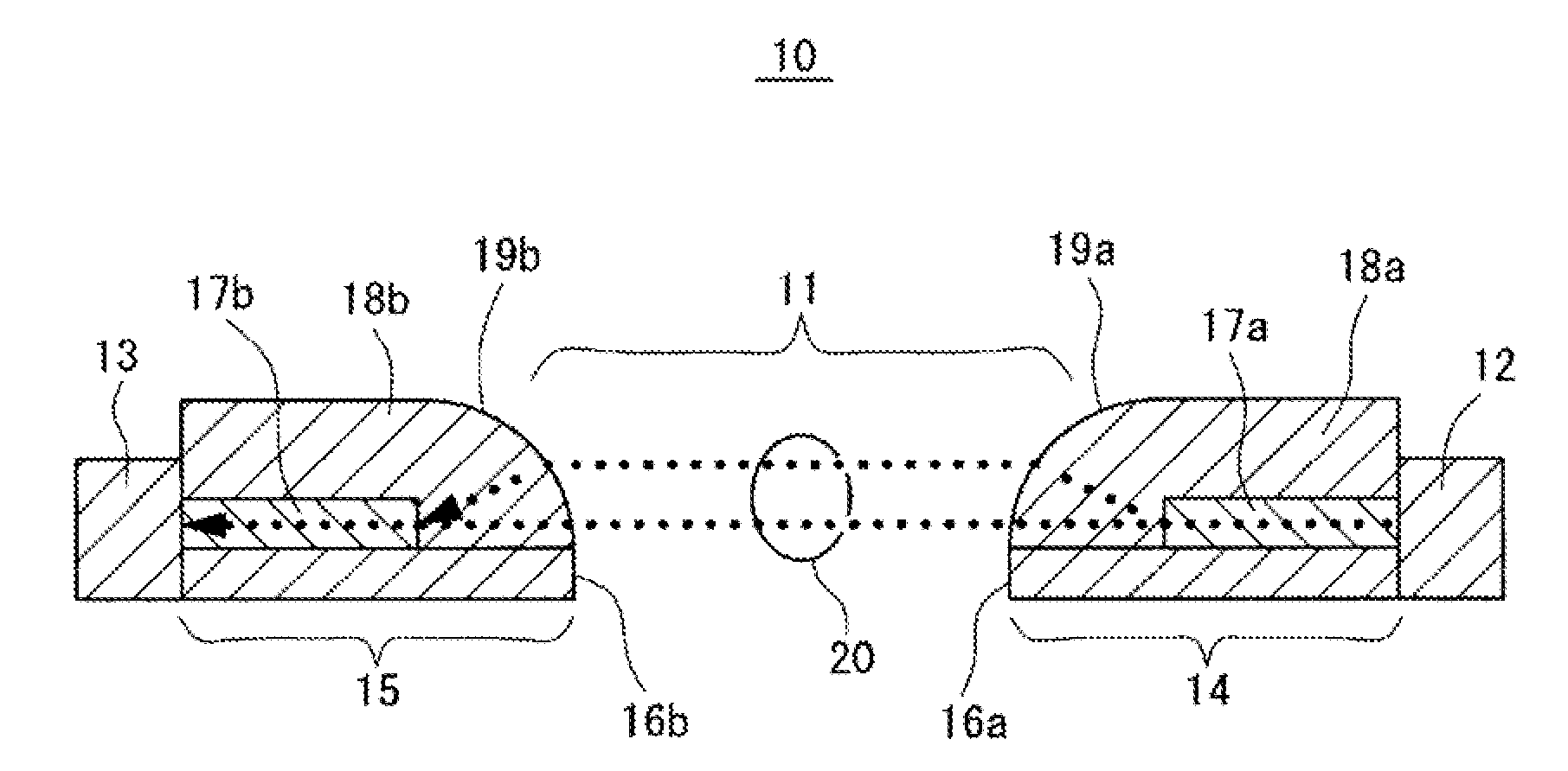
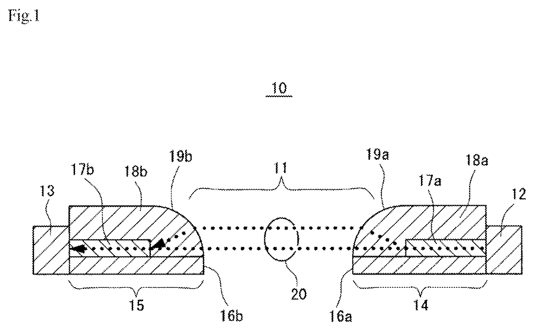
[0013]As described above, since the optical touch panel according to the present invention has a lens-integrated over-cladding layer, it is possible to eliminate the necessity for performing lens assembly and optical axis alignment and therefore to eliminate the fear that the displacement of lenses will occur. This makes it possible to achieve high optical transmission efficiency and high impact resistance.

Problems solved by technology

However, such a conventional optical touch panel uses a large number of optical parts, such as mirrors and lenses or the like, and therefore requires complicated assembly and alignment.
Further, displacement of such optical parts is likely to occur, and there is a case where high optical transmission efficiency cannot be achieved.

Method used


Image

  • Optical touch panel and method for manufacturing the same
  • Optical touch panel and method for manufacturing the same
  • Optical touch panel and method for manufacturing the same

Examples


examples

[0045]A varnish for forming cladding was prepared by mixing 35 parts by weight of bisphenoxyethanolfluorene glycidyl ether (component A), 40 parts by weight of an alicyclic epoxy resin (CELLOXIDE 2021P manufactured by Daicel Chemical Industries, Ltd.) (component B), 20 parts by weight of an alicyclic epoxy resin having a cyclohexene oxide skeleton (CELLOXIDE 2081 manufactured by Daicel Chemical Industries, Ltd.) (component C), and 2 parts by weight of a 50% propione carbonate solution of 4,4′-bis[di(β-hydroxyethoxy)phenylsulfinio]phenylsulfide-bis-hexafluoroantimonate (component D).

[0046]A varnish for forming cores was prepared by mixing 70 parts by weight of the component A, 30 parts by weight of 1,3,3-tris(4-(2-(3-oxetanyl)butoxyphenyl)butane, 1 part by weight of the component D, and 35 parts by weight of ethyl lactate.

[0047]The varnish for forming cladding was applied onto the surface of a polyethylene naphthalate film having a thickness of 188 μm, irradiated with UV light at 200...


PUM


Abstract

An optical touch panel having over-cladding layers each integrated with a lens-shaped portion (i.e., optical waveguides each having a lens-integrated over-cladding layer). The optical touch panel requires neither lens assembly nor optical axis alignment, and is therefore free from the fear that the displacement of lenses will occur. This makes it possible to achieve high optical transmission efficiency and high impact resistance.

Description

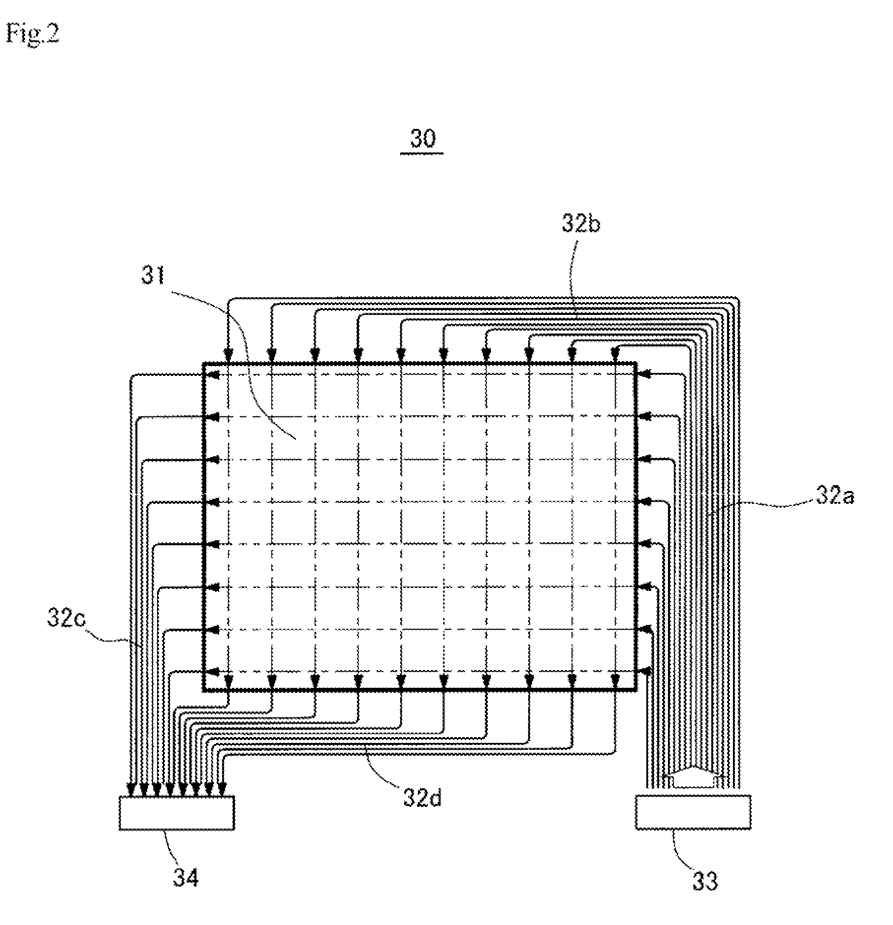
BACKGROUND OF THE INVENTION[0001]1. Field of the Invention[0002]The present invention relates to an optical touch panel which enables coordinate input by a finger or a pen and includes a display screen (i.e., a coordinate input region), such as a liquid crystal panel or the like, and a light-emitting element, a light-receiving element, and an optical waveguide which are provided around the display screen.[0003]2. Description of Related Art[0004]A known conventional optical touch panel (i.e., a coordinate input device) includes an optical waveguide and microlenses (see, for example, Japanese Unexamined Patent Publication No. 2004-295644). An optical waveguide is light in weight and enables high-speed signal transmission, and is therefore expected to be used in various electronic devices in future. However, such a conventional optical touch panel uses a large number of optical parts, such as mirrors and lenses or the like, and therefore requires complicated assembly and alignment. Fur...

Claims


Application Information

Patent Timeline
IPC IPC(8): G02B6/32B29D11/00
CPCG02B6/12004G02B6/1221G02B6/1245G06F3/0421G02B2006/12102G02B2006/1219G02B6/138G06F3/0304
Inventor JUNI, NORIYUKI
Owner NITTO DENKO CORP
Why Eureka
Eureka Blog
Learn More