Impeller assembly for centrifugal pumps

a centrifugal pump and assembly technology, applied in the direction of liquid fuel engines, vessel construction, marine propulsion, etc., can solve the problems of inability the time period required to complete the self-priming process of centrifugal pumps may be undesired long

Inactive Publication Date: 2003-12-18
HACKETT WILLIAM FRANKLIN JR
View PDF3 Cites 153 Cited by
  • Summary
  • Abstract
  • Description
  • Claims
  • Application Information

AI Technical Summary

Problems solved by technology

A drawback of centrifugal pumps is that they must be "primed" prior to use.
Although self-priming centrifugal pumps (i.e., a centrifugal pump that is configured to automatically remove [evacuate] air from the suction inlet and that may handle liquids, gases and liquid-gas mixtures) are known, the time period required to complete a self-priming process in such self-priming centrifugal pumps may be undesirably long.

Method used


Image

  • Impeller assembly for centrifugal pumps
  • Impeller assembly for centrifugal pumps
  • Impeller assembly for centrifugal pumps

Examples


Embodiment Construction

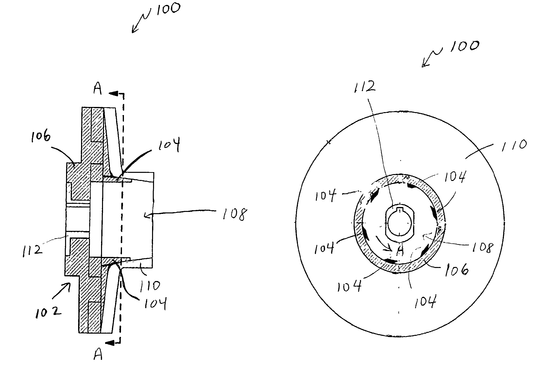
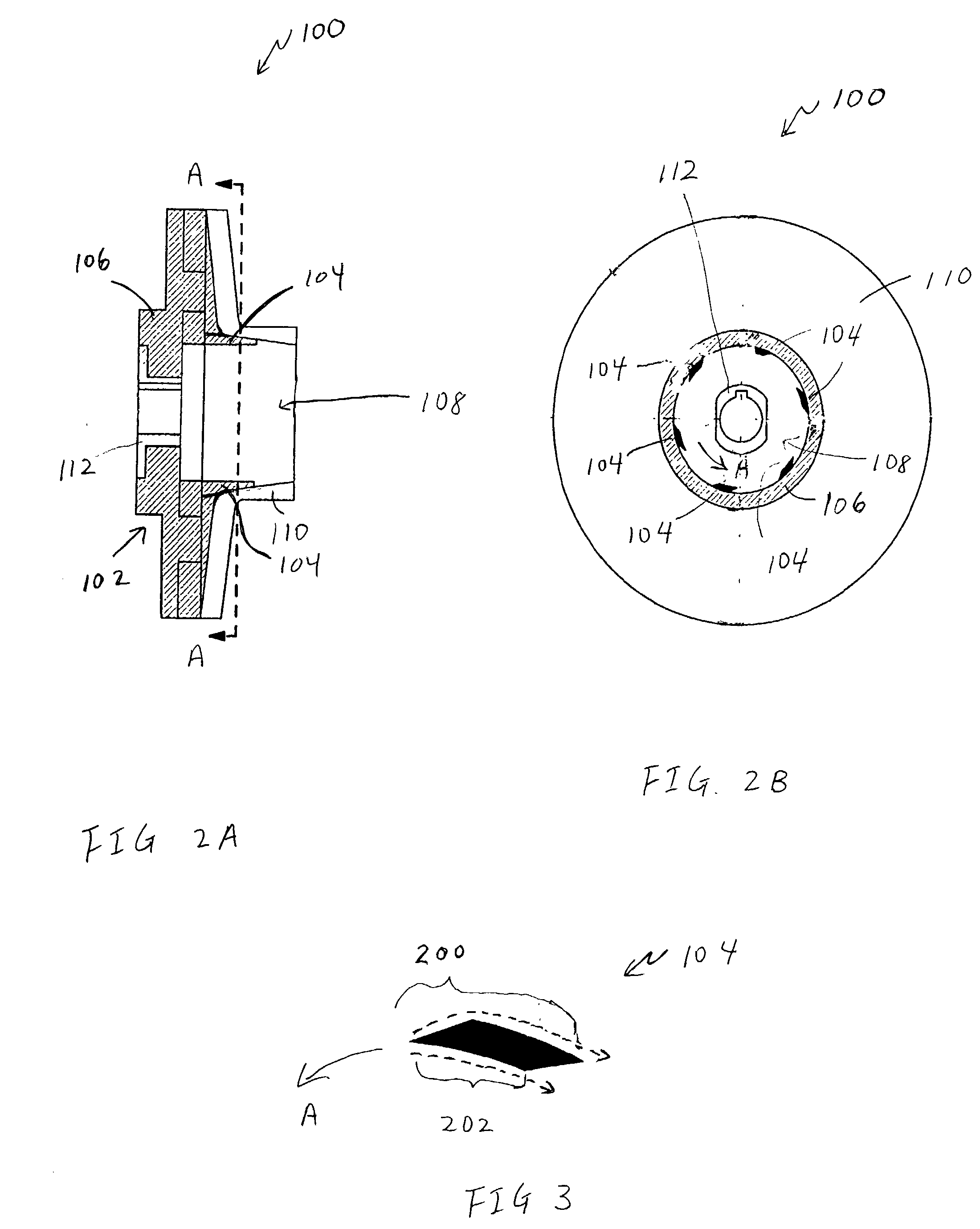
[0019] FIGS. 2A and 2B are simplified depictions of an impeller assembly 100 for use in a centrifugal pump in accordance with one exemplary embodiment of the present invention. Impeller assembly 100 includes an impeller 102 and six winglets 104 (shown in cross-section in FIG. 3). Impeller 102 includes a first impeller body 106 with an eye opening 108 therein, a second impeller body 110 (through which eye opening 108 also passes) and a keyway 112. Eye opening 108 is configured for the passage of fluid (e.g., water) therethrough when impeller assembly 100 is in use in a centrifugal pump.

[0020] Winglets 104 are configured to protrude within eye opening 108 (see, for example, FIG. 2B) of impeller 102 and are also configured for movement in a predetermined pattern (e.g., the circular pattern indicated by arrow A of FIGS. 2B and 3) when impeller assembly 100 is in use in a centrifugal pump.

[0021] Referring to FIGS. 4A-4C, first impeller body 106 includes six curved vanes 114 disposed with...


PUM


Abstract

An impeller assembly for centrifugal pumps that enables self-priming in a relatively short time period includes an impeller and at least one winglet (e.g., six winglets with a trapezium cross-sectional shape). The impeller includes an impeller body with an eye opening therein. The eye opening is configured for the passage of a fluid (e.g., water) therethrough when the impeller assembly is in use. The impeller body also includes at least one vane, with a leading end, disposed about the eye opening. The at least one winglet is positioned to protrude into the eye opening of the impeller body and may, for example, be coupled to the leading end of the vane.

Description

[0001] 1. Field of the Invention[0002] The present invention relates, in general, to pump assemblies and, in particular, to impeller assemblies for centrifugal pumps.[0003] 2. Description of the Related Art[0004] Centrifugal pumps are widely used in chemical, food, irrigation and other industries to pump a variety of liquids (e.g., water) and liquid-solid mixtures. Centrifugal pumps are a type of kinetic energy pump that imparts energy to a liquid through centrifugal force produced by a rotating impeller. The energy is used to increase the pressure of the liquid and move the liquid from one point to another.[0005] FIG. 1 is a simplified cross-sectional depiction of a conventional centrifugal pump 10 that includes a stationary casing 12 and an impeller 14 with curved vanes 16 (also referred to as "blades" and shown as lines for simplicity) and an axially-disposed eye opening 18. Rotation of impeller 14, and thus curved vanes 16, (e.g., by a motor [not shown] operatively coupled to im...

Claims


Application Information

Patent Timeline
Patent Type & Authority Applications(United States)
IPC IPC(8): F04D9/02F04D29/22
CPCF04D29/2261F04D9/02
Inventor SNIDER, PHILLIP
Owner HACKETT WILLIAM FRANKLIN JR
Why Eureka
Try Eureka