Devices with multiple organic-metal mixed layers

a technology of organic metal and mixed layers, applied in the direction of discharge tube/lamp details, discharge tube luminescnet screens, other domestic articles, etc., can solve the problems of high reactivity, high reflected illumination ratio, and "washout" of displayed images

Inactive Publication Date: 2003-12-25
LG DISPLAY CO LTD
View PDF33 Cites 113 Cited by
  • Summary
  • Abstract
  • Description
  • Claims
  • Application Information

AI Technical Summary

Problems solved by technology

When viewed under high ambient illumination, the reflective back electrode reflects a substantial amount of the ambient illumination to the observer, which results in higher ratios of reflected illumination as compared to the device's own emission resulting in "washout" of the displayed image.
Another problem of known organic light emitting devices originates from the use of metals with low work functions, and hence high reactivity, in the cathodes.
Due to their high reactivity, such cathode materials are unstable in ambient conditions and react with atmospheric O.sub.2 and water to form non-emissive dark spots.

Method used


Image

  • Devices with multiple organic-metal mixed layers
  • Devices with multiple organic-metal mixed layers
  • Devices with multiple organic-metal mixed layers

Examples


examples 1-73

Comparative Examples Indicated With "C")

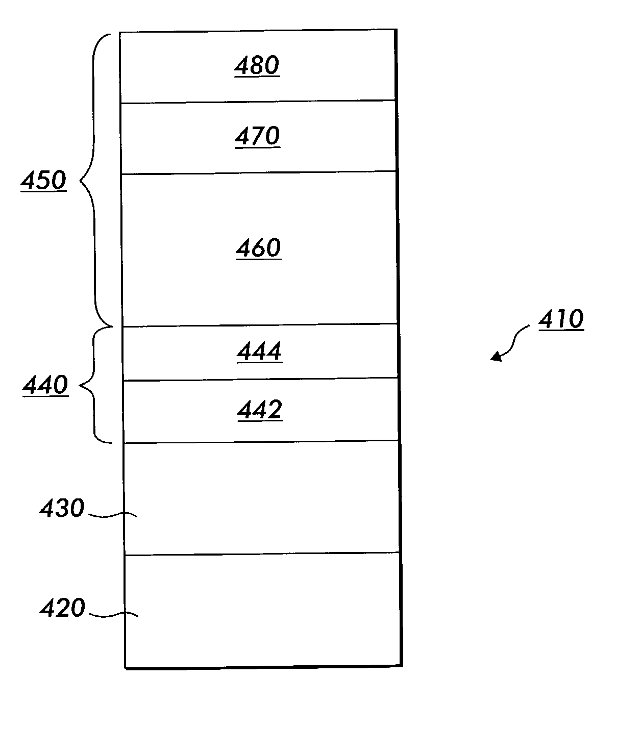
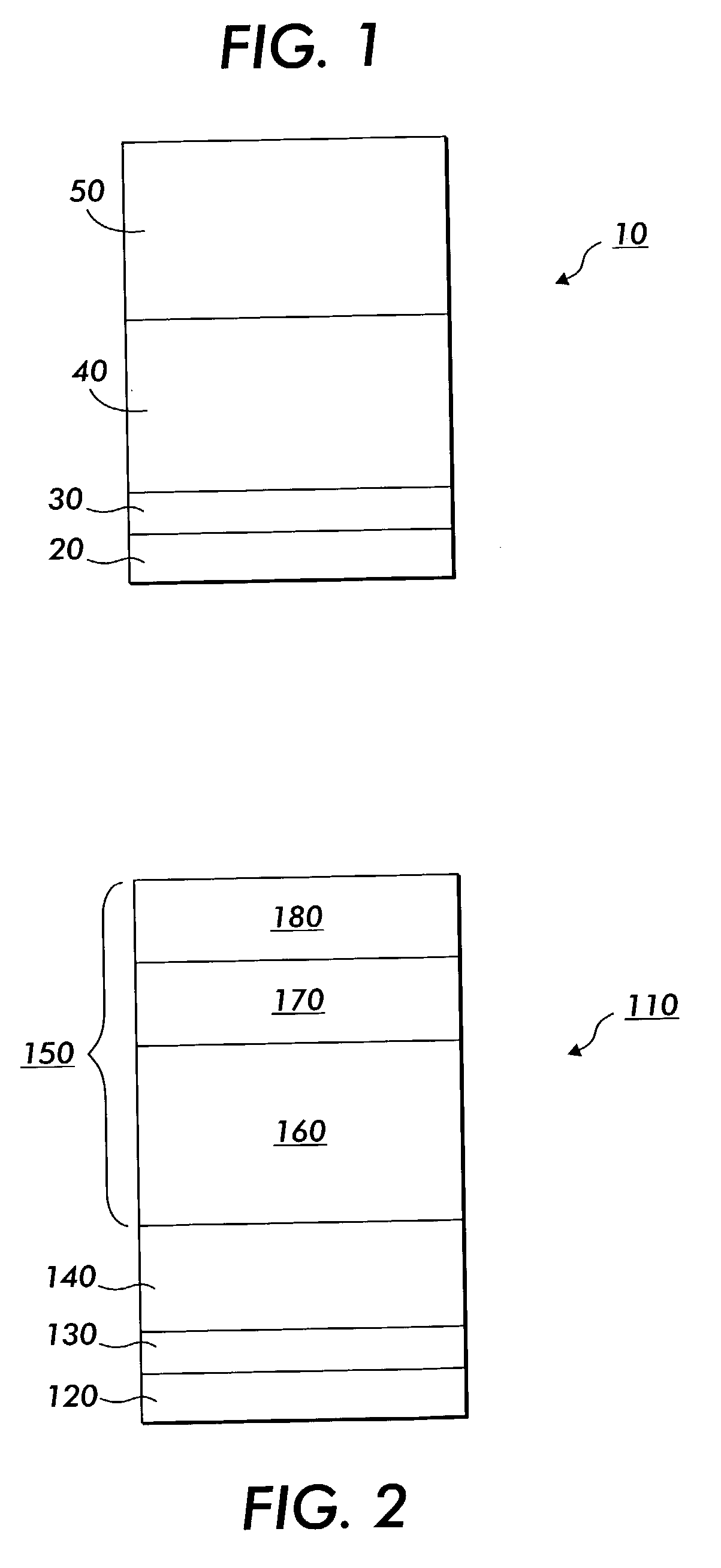
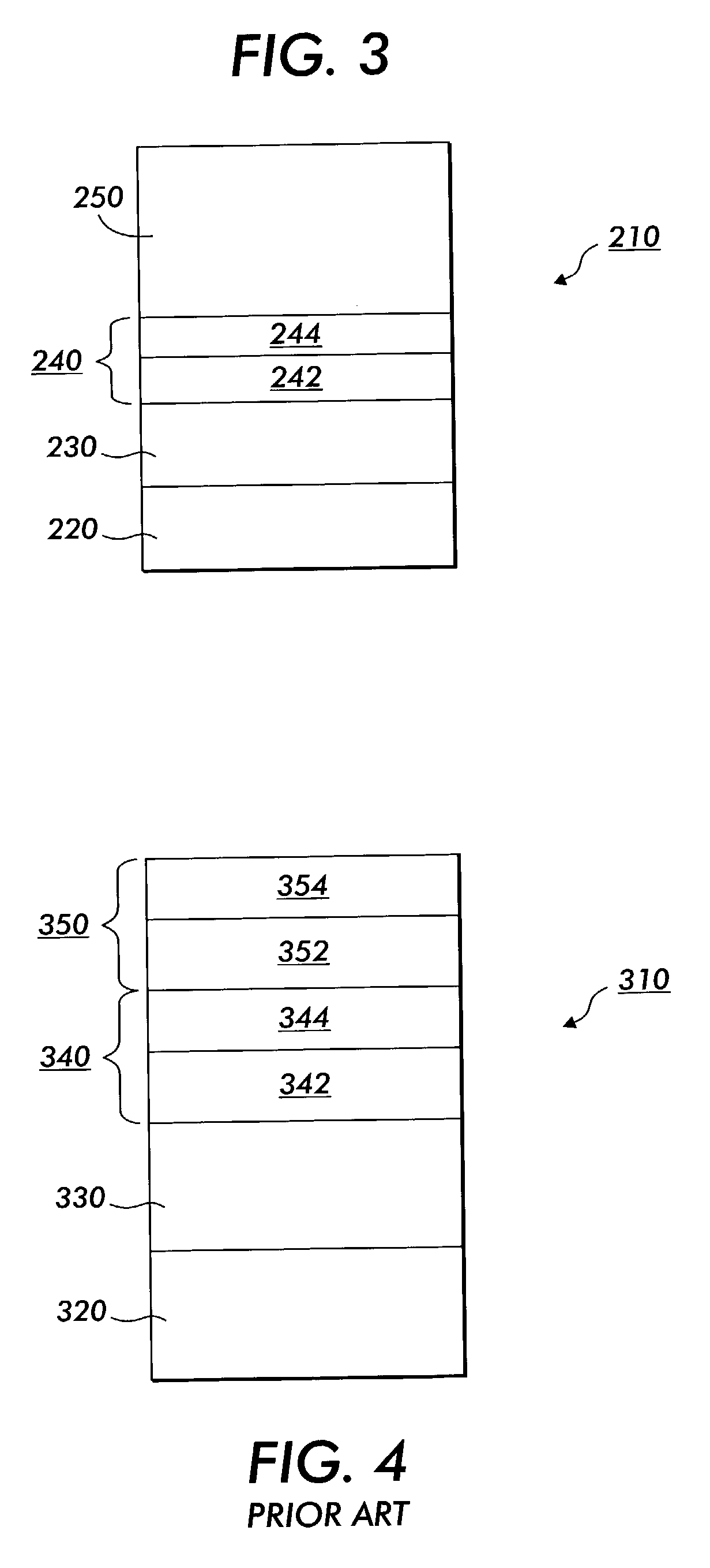
[0250] Examples 1-51 in the first Table and 52-73 in the second Table below summarize inventive OLED devices that have been reduced to practice. All devices were fabricated using physical vapor deposition in vacuum (5.times.10.sup.-6 Torr) on ITO-coated glass substrates, that were pre-cleaned using UV-ozone cleaning. The numbers in parentheses refer to layer thickness in Angstroms. In examples 1-51, the reduced reflectance of the inventive devices, utilizing a variety of luminescent region configurations, is observed in the lower values in the "% Reflection" column, in comparison to those of the comparative devices. In Examples 52-73, the reduced reflectance of inventive devices with multiple MOMLs, all utilizing the same luminescent region configuration, is observed in the lower value in the "Sun / Eye-weighted Integrated % Reflectivity (SEIR)" in comparison to those of comparative devices (devices without MOML or with a single MOML). In exampl...

examples 1a-23a

[0251] Examples 1A-23A in the third Table below summarize other inventive OLED devices that can be prepared using the same procedures as for Examples 1-51. The numbers in parentheses refer to layer thickness in Angstroms. Examples 1A-23A are "paper examples" that have not been reduced to practice.

[0252] In the tables below, the following are used:

[0253] PeDot: Polythiophene;

[0254] TPD: N. N '-diphenyl-N. N'-bis(3-methylphenyl)-1,1-biphenyl-4,4'-di- amine);

[0255] CuPc: Copper Phthalocyanine;

[0256] NPB: N,N'di(naphthalene-1-yl)-N,N'-diphenyl-benzidine);

[0257] AlQ3: tris(8-hydroxyquinoline) aluminum; dopant: any dopant such as C545T and PtOEP;

[0258] ITO: Indium-Tin-Oxide;

[0259] MeNIC: 2,8-dimethyl-5,11-di-1-naphthyl-5,11-dihydroindolo[3,2-b]car- bazole;

[0260] T1: 4,4'-bis[2-(4,6-diphenyl-1,3,5-triazinyl)]-1,1'-biphenyl);

[0261] Perinone black pigment: Bis (1,8-Naphthimidazo) perinone; PtOEP: 2,3,7,8,12,13,17,18-octaethyl-21H,23H-porphine platinum (II); and C545T: 10-2-(benzothiazolyl)-2...


PUM

PropertyMeasurementUnit
work functionaaaaaaaaaa
temperaturesaaaaaaaaaa
thicknessaaaaaaaaaa

Abstract

A display device composed of: (a) a cathode; (b) an anode; (c) a luminescent region between the cathode and the anode; and (d) an optional region adjacent to the cathode or the anode, wherein the device includes a plurality of metal-organic mixed layers disposed at one or more of the cathode, the anode, the luminescent region and the optional region, wherein each of the metal-organic mixed layers includes: (i) an inorganic metal containing material, and (ii) an organic material.

Description

CROSS REFERENCE TO RELATED APPLICATIONS[0001] This application is a continuation-in-part application of pending parent U.S. application Ser. No. 10 / 117,812 (filed Apr. 5, 2002), from which priority is claimed, the disclosure of which is totally incorporated herein by reference. U.S. application Ser. No. 10 / 117,812 was published as U.S. patent application Publication No. US 2002 / 0180349 A1.[0002] U.S. application Ser. No. 10 / 117,812 is a continuation-in-part application of U.S. application Ser. No. 09 / 800,716 (filed Mar. 8, 2001; now abandoned).BACKGROUND OF THE INVENTION[0003] Organic light emitting devices (OLEDs) represent a promising technology for display applications. A typical organic light emitting device includes a first electrode; a luminescent region comprising one or more electroluminescent organic material(s); and a second electrode; wherein one of the first electrode and the second electrode functions as a hole-injecting anode, and the other electrode functions as an el...

Claims


Application Information

Patent Timeline
Patent Type & Authority Applications(United States)
IPC IPC(8): H01L51/50H01L51/52
CPCH01L51/5012H01L51/5231Y10S428/917H01L51/5281H10K50/826H10K50/86H10K50/11
Inventor AZIZ, HANYNORRIS, RYANPOPOVIC, ZORAN D.PAINE, ANTHONY J.COGGAN, JENNIFER A.HU, NAN-XING
Owner LG DISPLAY CO LTD
Why Eureka
Try Eureka