Spinal implant including a compressible connector

a technology applied in the field of spine implants and connectors, can solve the problems of pain and/or nerve damage, subsidence or deformation of vertebrae, and alteration of the natural separation distance between adjacent vertebra

Inactive Publication Date: 2004-01-01
ZIMMER SPINE INC
View PDF99 Cites 178 Cited by
  • Summary
  • Abstract
  • Description
  • Claims
  • Application Information

AI Technical Summary

Problems solved by technology

Partial or full removal of an intervertebral disc may destabilize the spinal column resulting in subsidence or deformation of vertebrae.
Destabilization of a spinal column may result in alteration of a natural separation distance between adjacent vertebrae.
Excessive pressure applied to the nerves may cause pain and / or nerve damage.
Impacting an implant may be dangerous and may not inhibit an inserted implant from backing out of a disc space after insertion.
Distracting the adjacent vertebrae a distance that allows a spinal implant to be inserted into a disc space, however, may not be desirable.
Imperfect elastic characteristics of connective tissue may not allow connective tissue to return to a pre-distracted state after the distraction device is removed.
During some implant insertion procedures, a disc space may be too small to allow for insertion of implant members coupled to a spreader without protrusions of the implant members scarring surfaces of adjacent vertebrae during insertion.

Method used


Image

  • Spinal implant including a compressible connector
  • Spinal implant including a compressible connector
  • Spinal implant including a compressible connector

Examples


Embodiment Construction

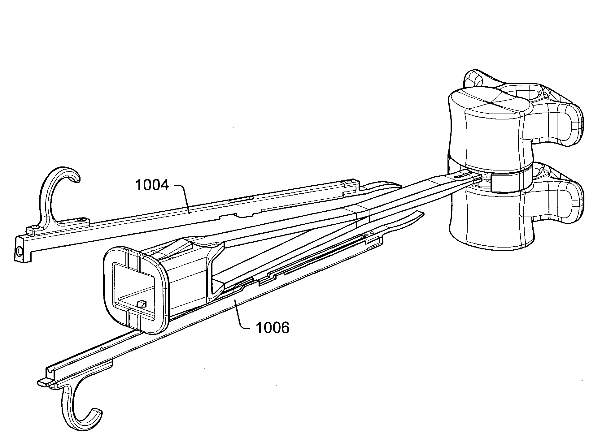
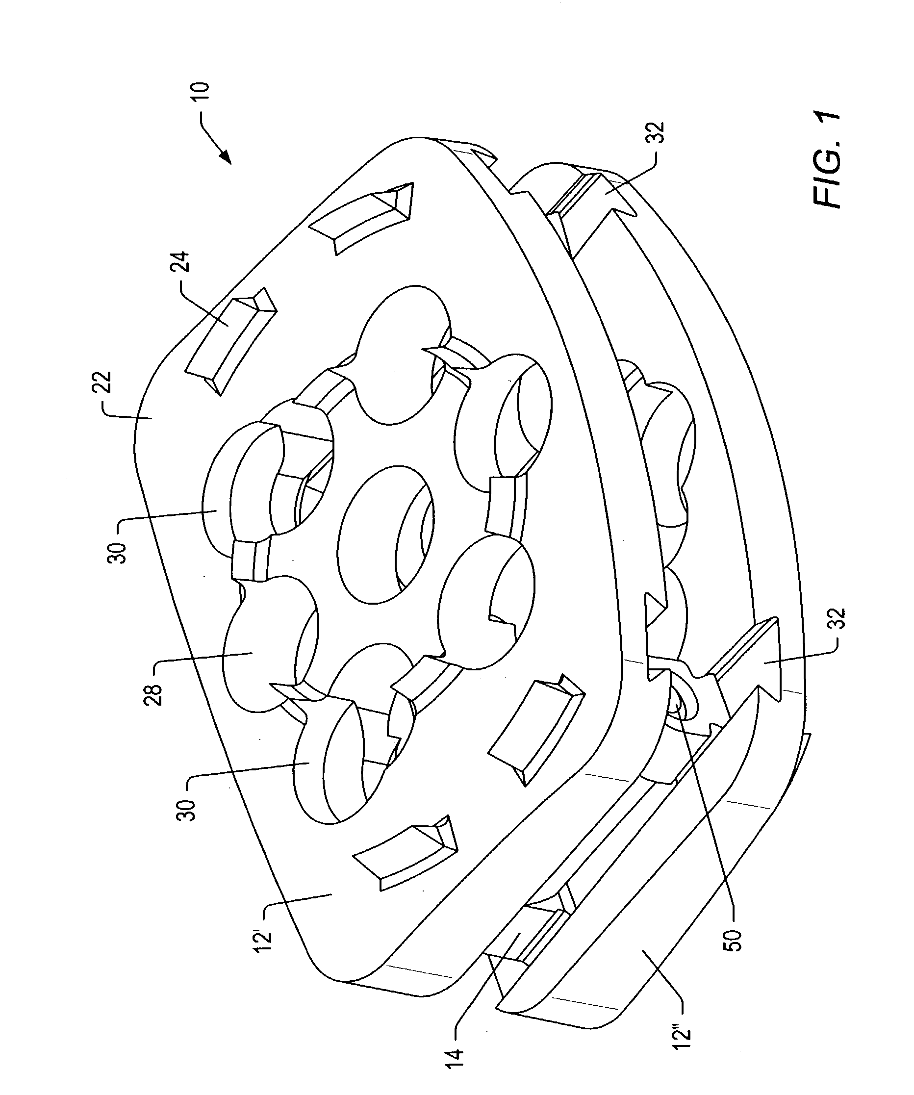
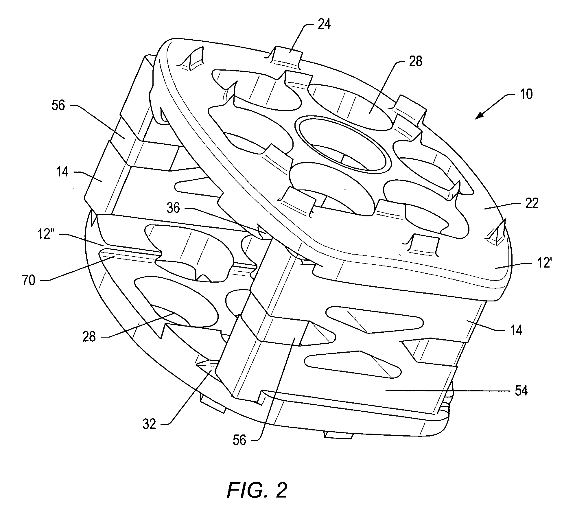
[0085] Referring to the drawings, FIG. 1 and FIG. 2 show perspective views of embodiments of implants 10. An implant may include members and a spacer between the members. The members may be implant members that contact surfaces of bone that are to be joined together by the implant. The spacer may establish a desired distance between the members. The spacer may be a formed of one or more components. In some embodiments, implant 10 may be a spinal implant. In some embodiments, the spinal implant may be a fusion device that promotes bone growth between vertebrae to fuse the vertebrae together. In some embodiments, the spinal implant may be an artificial disc that joins two vertebrae together while still allowing for at least some motion of the vertebrae relative to each other. In some embodiments, the implant may be an implant that joins and promotes fusion of two portions of a bone (e.g., a femur).

[0086] Implant 10 may include a pair of implant members 12 and connector or connectors 1...


PUM

PropertyMeasurementUnit
forceaaaaaaaaaa
heightaaaaaaaaaa
heightaaaaaaaaaa

Abstract

An implant may be formed in a disc space during a spinal fusion procedure. The implant may include implant members and connectors. The connectors may include sections with removed material that allow for some flexibility of the connectors. The connectors may include limiters that limit the amount of flexibility of the connectors. The ability of the connectors to flex may allow stress to be applied to bone growth material positioned in the implant. Stress may promote desirable bone growth.

Description

PRIORITY CLAIM[0001] This application claims priority to U.S. Provisional Application No. 60 / 363,219 entitled "Instrumentation And Procedure For Implanting Fusion Devices," filed Mar. 11, 2002. The above-referenced provisional application is incorporated by reference as if fully set forth herein.[0002] 1. Field of the Invention[0003] The present invention generally relates to the field of medical implants and more particularly to spinal implants. An embodiment of the invention relates to connectors for joining implants members of an implant together.[0004] 2. Description of Related Art[0005] An intervertebral disc may be subject to degeneration. Degeneration may be caused by trauma, disease, and / or aging. An intervertebral disc that becomes degenerated may have to be partially or fully removed from a spinal column. Partial or full removal of an intervertebral disc may destabilize the spinal column resulting in subsidence or deformation of vertebrae. Destabilization of a spinal colum...

Claims


Application Information

Patent Timeline
Patent Type & Authority Applications(United States)
IPC IPC(8): A61B17/02A61B19/00A61F2/00A61F2/02A61F2/28A61F2/30A61F2/44A61F2/46
CPCA61B17/0206A61F2002/4687A61B2017/0256A61B2019/462A61F2/28A61F2/442A61F2/447A61F2/4611A61F2/4657A61F2/4684A61F2002/2835A61F2002/30062A61F2002/30266A61F2002/30385A61F2002/30387A61F2002/30471A61F2002/305A61F2002/30507A61F2002/30565A61F2002/30616A61F2002/30713A61F2002/30714A61F2002/30784A61F2002/30823A61F2002/30848A61F2002/30924A61F2002/30925A61F2002/30927A61F2002/4623A61F2002/4627A61F2002/4628A61F2002/4629A61F2002/4662A61F2002/4681A61F2210/0004A61F2220/0025A61F2220/0091A61F2230/0082A61F2250/0087A61F2250/0089A61F2310/00017A61F2310/00023A61F2310/00179A61F2310/00407A61F2310/00796A61F2310/00976A61F2310/00359A61B17/025A61B2090/062A61F2002/3071A61F2002/30922A61F2002/30845A61F2/4603
Inventor LANDRY, MICHAEL E.TODD, RONALD C.WAGNER, ERIK J.HOCHSCHULER, STEPHEN H.
Owner ZIMMER SPINE INC
Why Eureka
Try Eureka