System and method for spinal fixation

a spinal fixation and system technology, applied in the field of medical devices, can solve the problems of high cost, inability to fix the spine, and inability to fix the vertebrae and associated connective elements, and achieve the effects of improving the growth rate of bone growth and the quality of the joint formed between the fixated bones, stabilizing the spine, and improving the quality of the join

Inactive Publication Date: 2010-12-30
INTERVENTIONAL SPINE
View PDF100 Cites 126 Cited by
  • Summary
  • Abstract
  • Description
  • Claims
  • Application Information

AI Technical Summary

Benefits of technology

[0009]Although spinal fusion is a highly documented and proven form of treatment in many patients, it is contemplated that the rate of bone growth and the quality of the joint formed between fixated bones can be improved. Further, notwithstanding the variety of efforts in the prior art described above, these techniques are associated with a variety of disadvantages. In particular, these techniques typically involve an open surgical procedure, which results in higher cost, lengthy in-patient hospital stays and the pain associated with open procedures. Therefore, there remains a need for improved techniques and systems for stabilization of the spine. Preferably, the devices are implantable through a minimally invasive procedure.
[0011]Various embodiments disclosed herein can be performed during a surgical procedure in which a bone fixation device and / or on graft material is implanted into a given portion of the spinal column. However, it is noted that the methods and apparatuses disclosed herein can also be used in bone fixation procedures other than those occurring in the spinal column. Continuing, various embodiments can comprise decorticating at least a portion of a bone structure used to be fixated relative to their bone structure. Additionally, each of the bone structure is to be fixated can be decorticated. As mentioned, in some embodiments, the decortication of the bone structure can be performed along with the implantation of a bone fixation device and / or bone graft material. It is contemplated that the effectiveness of these fixation procedure and its results can be substantially improved using embodiments disclosed herein.

Problems solved by technology

Additionally, the vertebrae and associated connective elements are subject to injuries, including fractures and torn ligaments and surgical manipulations, including laminectomies.
Further, notwithstanding the variety of efforts in the prior art described above, these techniques are associated with a variety of disadvantages.
In particular, these techniques typically involve an open surgical procedure, which results in higher cost, lengthy in-patient hospital stays and the pain associated with open procedures.

Method used


Image

  • System and method for spinal fixation
  • System and method for spinal fixation
  • System and method for spinal fixation

Examples


Embodiment Construction

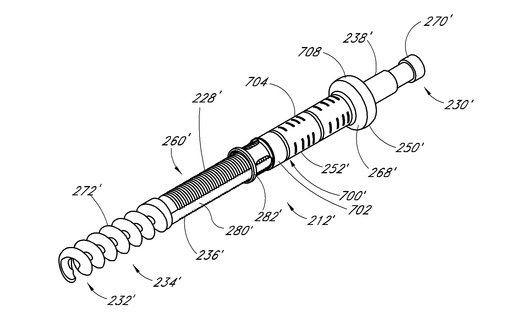
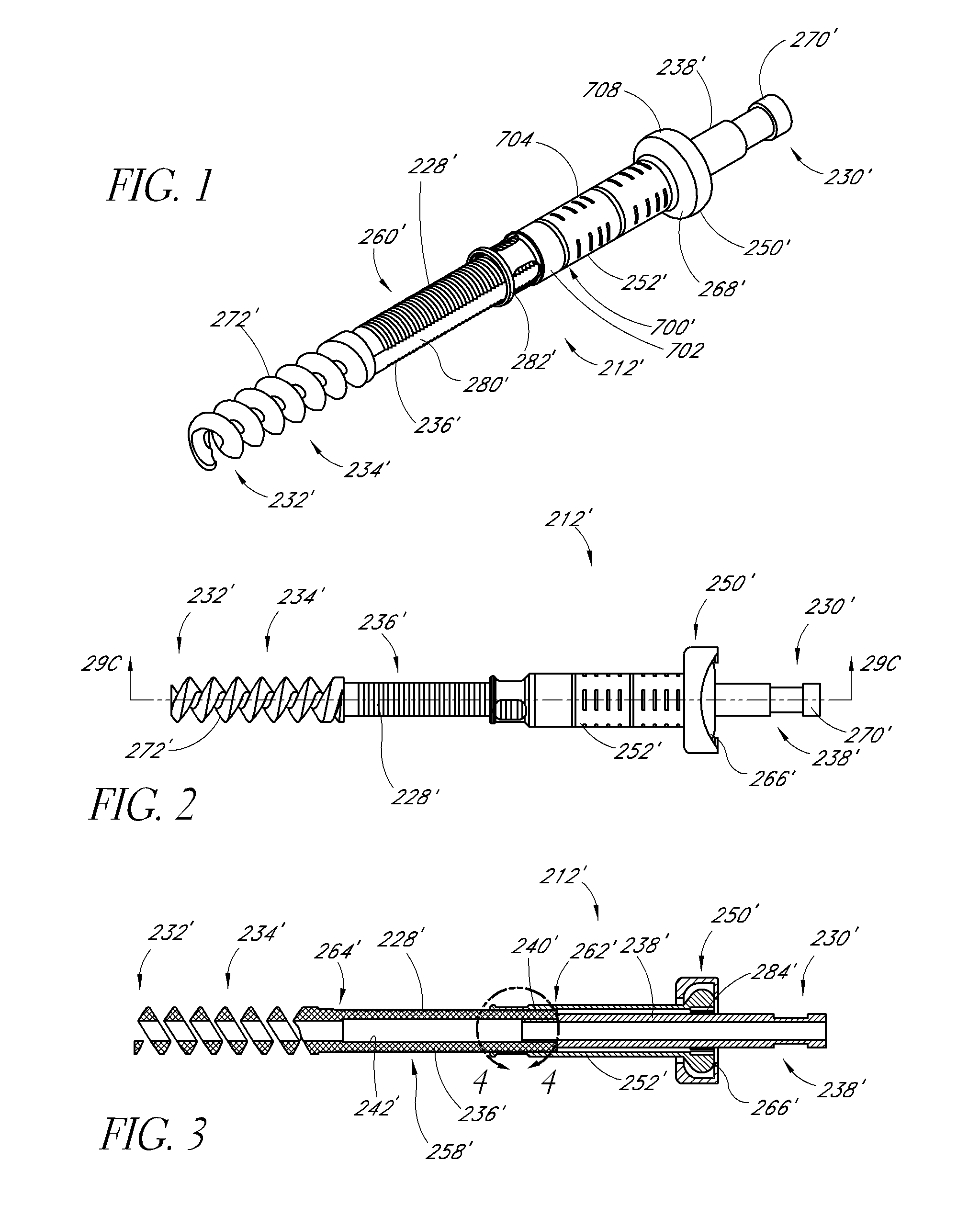
[0029]Although the application of the present inventions will be initially disclosed in connection with the spinal fixation devices and procedures illustrated in FIGS. 1-12, the methods and structures disclosed herein are intended for application in any of a wide variety of bones, fixations, and fractures, as will be apparent to those of skill in the art in view of the disclosure herein.

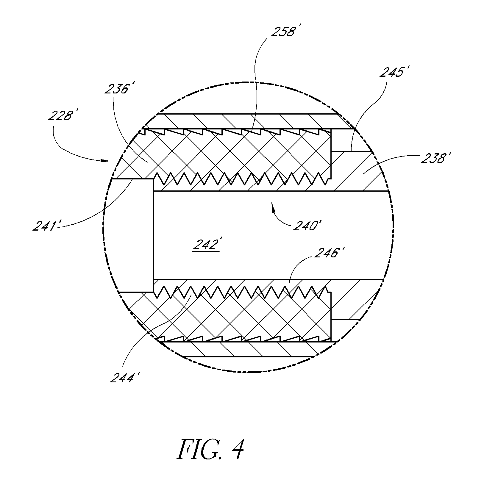
[0030]FIGS. 1-4 illustrate an embodiment of a fixation device 212′ having a body 228′ and proximal anchor 700′. In this embodiment, the body 228′ comprises a first portion 236′ and a second portion 238′ that are coupled together at a junction 240′ (FIG. 4). In the illustrated embodiment, the first portion 236′ carries the distal anchor 234′ while the second portion 238′ forms the proximal end 230′ of the body 228′. The first and second portions 236′, 238′ are preferably detachably coupled to each other at the junction 240′. In the illustrated embodiment, the first and second portions 236′, 238′ are d...


PUM


Abstract

A system and method of bone fixation are provided for improving the bone growth and stability of the fixated bones. For example, a target site for a bone fixation procedure can be accessed at a facet of a first vertebra using a tissue dilator. Bone material can be disrupting from or at the target site, and a bone fixation device can be installed to fix the first vertebra relative to a second vertebra. The disruption and / or removal of the bone material, such as by rasping facets or a facet joint of the first vertebra and the second vertebra, can tend to promote bone growth. Further, it is contemplated that bone graft material can be inserted at the target site, such as into a joint space formed between facets of the first vertebra and the second vertebra.

Description

CROSS-REFERENCE TO RELATED APPLICATIONS[0001]The present application claims priority under 35 U.S.C. §119(e) to U.S. Provisional Application No. 61 / 220,172 filed on Jun. 24, 2009, the disclosure of which, including the Appendix, is incorporated by reference herein in its entirety.BACKGROUND[0002]1. Field of the Inventions[0003]The present inventions relate to medical devices and, more particularly, to methods and apparatuses for spinal fixation.[0004]2. Description of the Related Art[0005]The human spine is a flexible weight bearing column formed from a plurality of bones called vertebrae. There are thirty-three vertebrae, which can be grouped into one of five regions (cervical, thoracic, lumbar, sacral, and coccygeal). Moving down the spine, there are generally seven cervical vertebrae, twelve thoracic vertebrae, five lumbar vertebrae, five sacral vertebrae, and four coccygeal vertebrae. The vertebrae of the cervical, thoracic, and lumbar regions of the spine are typically separate...

Claims


Application Information

Patent Timeline
Patent Type & Authority Applications(United States)
IPC IPC(8): A61B17/88A61B17/86
CPCA61B17/1659A61B17/869A61B17/7064A61B17/1671
Inventor CULBERT, BRAD S.WARREN, CHRISTOPHERFLOWER, ROBERTOLMOS, FAUSTO
Owner INTERVENTIONAL SPINE
Why Eureka
Try Eureka