High-speed defrost refrigeration system

a refrigeration system and high-speed technology, applied in the direction of corrosion prevention, compression machines with several evaporators, compression machines, etc., can solve the problems of reducing the efficiency of evaporators, affecting the freshness and quality of foodstuffs, and obstructing the passage of air to maintain foodstuffs refrigerated

Inactive Publication Date: 2004-01-08
DUBE SERGE
View PDF5 Cites 21 Cited by
  • Summary
  • Abstract
  • Description
  • Claims
  • Application Information

AI Technical Summary

Benefits of technology

0007] It is a feature of the present invention to provide a high-speed defrost refrigeration system that operates a defrost of evaporators at low pressure.

Problems solved by technology

In refrigeration systems found in the food industry to refrigerate fresh and frozen foods, it is necessary to defrost the refrigeration coils of the evaporators periodically, as the refrigeration systems working below the freezing point of water are gradually covered by a layer of frost which reduces the efficiency of evaporators.
The evaporators become clogged up by the build-up of ice thereon during the refrigeration cycle, whereby the passage of air maintaining the foodstuff refrigerated is obstructed.
Exposing foodstuff to warm temperatures during long defrost cycles may have adverse effects on their freshness and quality.
The resulting defrost cycles may last up to about 40 minutes, thereby possibly fouling the foodstuff.
This also results in a fairly lengthy defrost cycle.
The compressors are affected by hot gas coming back through the suction header, thereby causing the compressors to overheat.
Furthermore, the energy costs increases with the compressor head pressure increase.

Method used


Image

  • High-speed defrost refrigeration system
  • High-speed defrost refrigeration system
  • High-speed defrost refrigeration system

Examples


Embodiment Construction

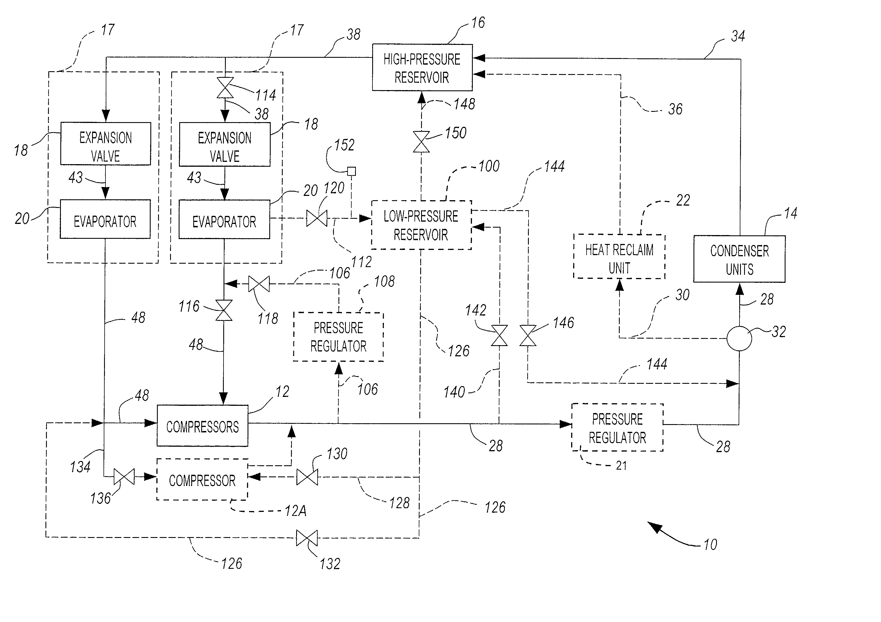
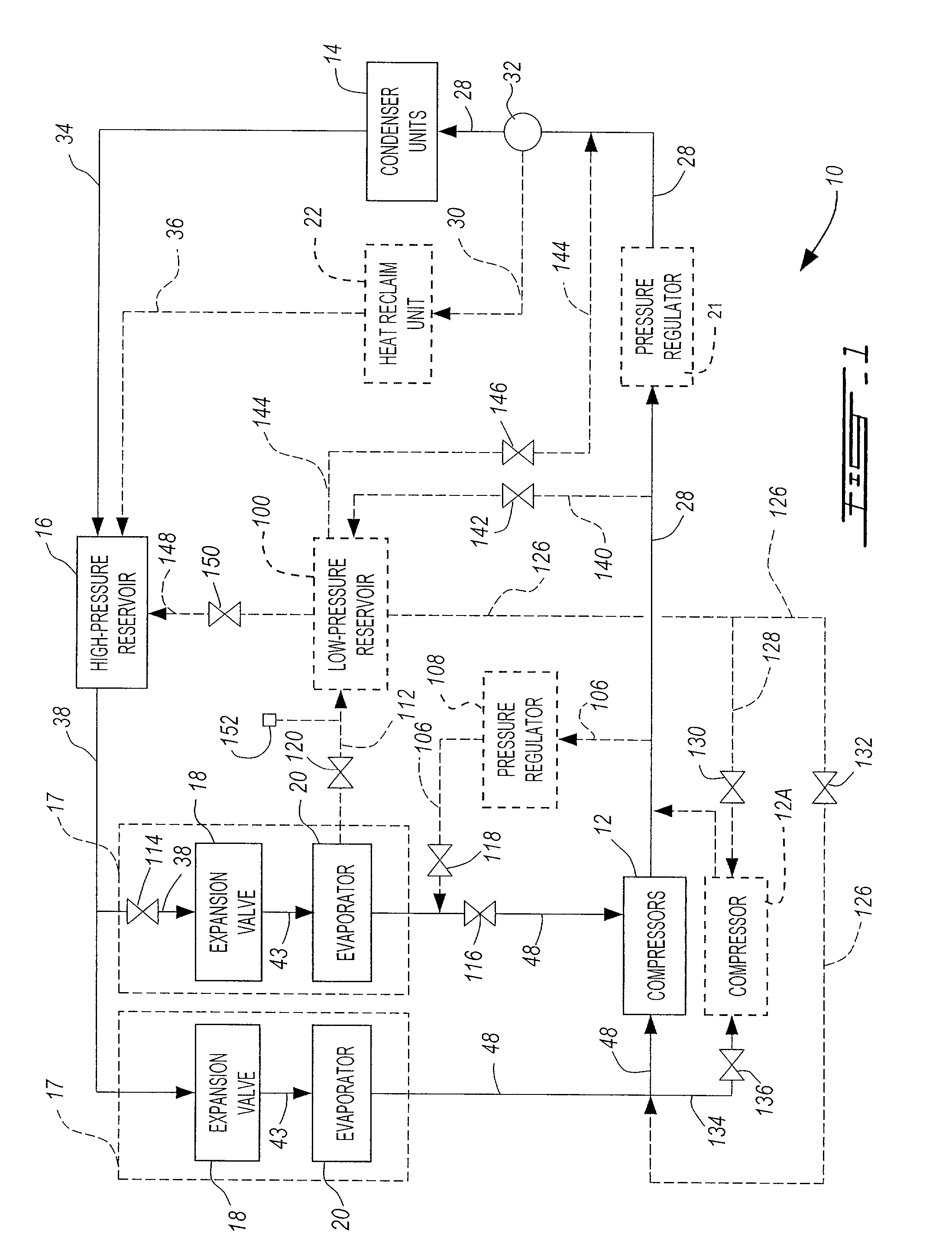
[0028] Referring to the drawings, and more particularly to FIG. 1, a refrigeration system in accordance with the present invention is generally shown at 10. The refrigeration system 10 comprises the components found on typical refrigeration systems, such as compressors 12 (one of which is 12A, for reasons to be described hereinafter), a high-pressure reservoir 16, expansion valves 18, and evaporators 20. The refrigeration system 10 is shown having a heat reclaim unit 22, which is optional. In FIG. 1, the refrigeration system 10 is shown having only two sets of evaporator 20 / expansion valve 18 for the simplicity of the illustration. It is obvious that numerous other sets of evaporator 20 / expansion valve 18 may be added to the refrigeration system 10.

[0029] The compressors 12 are connected to the condenser units 14 by lines 28. A pressure regulator 21 is in the line 28 but is not in operation during normal refrigeration cycles, and is thus normally open to enable refrigerant flow ther...


PUM


Abstract

A defrost refrigeration system having a main refrigeration system and comprising a first line extending from a compressing stage to an evaporator stage and adapted to receive refrigerant in high-pressure gas state from the compressing stage. A first pressure reducing device on the first line is provided for reducing a pressure of the refrigerant in the high-pressure gas state to a second low-pressure gas state. Valves are provided for stopping a flow of the refrigerant in a first low-pressure liquid state from a condensing stage to evaporators of the evaporator stage and directing a flow of the refrigerant in the second low-pressure gas state to release heat to defrost the evaporators and thereby changing phase at least partially to a second low-pressure liquid state. A second line is provided for directing the refrigerant having released heat to the compressing stage, the condensing stage or the evaporator stage.

Description

[0001] The present invention relates to a high-speed evaporator defrost system for defrosting refrigeration coils of evaporators in a short period of time without having to increase compressor head pressure.[0002] In refrigeration systems found in the food industry to refrigerate fresh and frozen foods, it is necessary to defrost the refrigeration coils of the evaporators periodically, as the refrigeration systems working below the freezing point of water are gradually covered by a layer of frost which reduces the efficiency of evaporators. The evaporators become clogged up by the build-up of ice thereon during the refrigeration cycle, whereby the passage of air maintaining the foodstuff refrigerated is obstructed. Exposing foodstuff to warm temperatures during long defrost cycles may have adverse effects on their freshness and quality.[0003] One method known in the prior art for defrosting refrigeration coils uses an air defrost method wherein fans blow warm air against the clogged...

Claims


Application Information

Patent Timeline
Patent Type & Authority Applications(United States)
IPC IPC(8): F25B5/02F25B41/00F25B43/00F25B47/02
CPCF25B5/02F25B41/00F25B43/006F25B2400/16F25B2341/0015F25B2400/0411F25B2400/075F25B47/022
Inventor DUBE, SERGE
Owner DUBE SERGE
Why Eureka
Try Eureka