Ejector cycle
a technology of ejector and cycle, which is applied in the direction of machine operation, transportation and packaging, light and heating apparatus, etc., can solve the problems of reducing the lubricating efficiency of the compressor, reducing the amount of lubricating oil returned to the compressor, and reducing the heat absorption performance of the evaporator
- Summary
- Abstract
- Description
- Claims
- Application Information
AI Technical Summary
Benefits of technology
Problems solved by technology
Method used
Image
Examples
first embodiment
[0041] (First Embodiment)
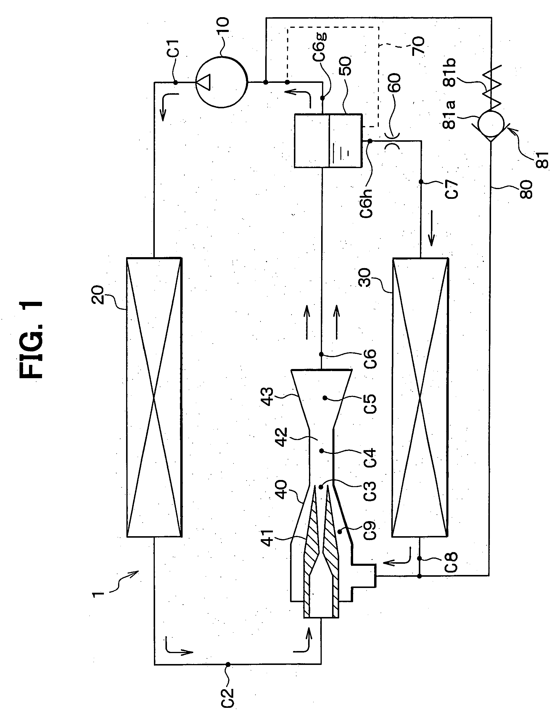
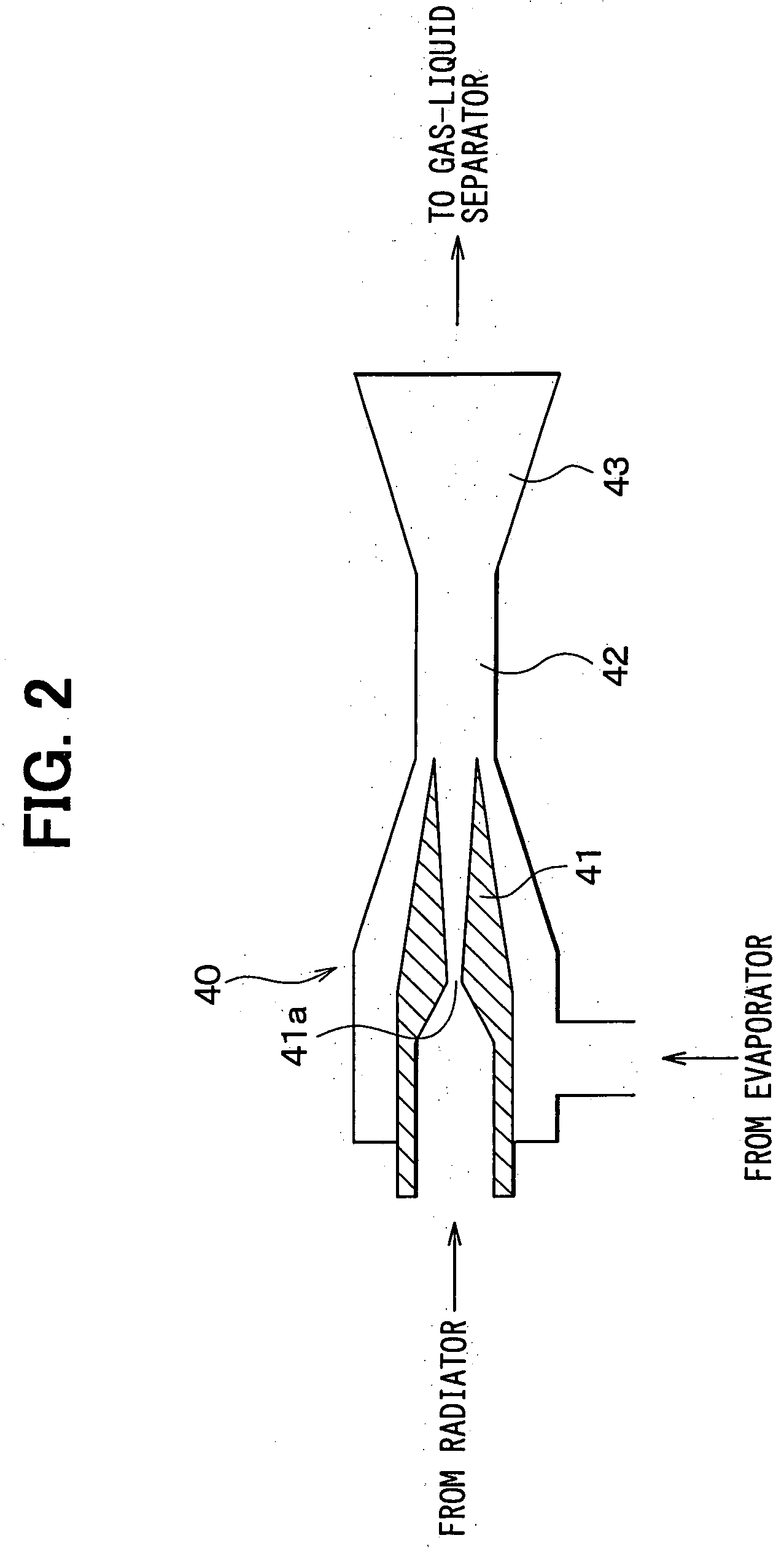
[0042] In the first embodiment, an ejector cycle according to the present invention is typically used for a vapor compression refrigerator used for a showcase for refrigerating foods. In FIG. 1, a compressor 10 is an electric compressor for sucking and compressing refrigerant circulated in an ejector cycle 1. A radiator 20 is a high-pressure heat exchanger for cooling high-temperature and high-pressure refrigerant discharged from the compressor 10 by performing heat-exchange operation between outside air and the high-temperature and high-pressure refrigerant. Further, an evaporator 30 is a low-pressure heat exchanger for cooling air to be blown into the showcase by evaporating liquid refrigerant, more specifically, by performing heat-exchange operation between the air and low-pressure refrigerant. An ejector 40 sucks refrigerant evaporated in the evaporator 30 while decompressing and expanding refrigerant flowing out from the radiator 20 in a nozzle 41, and ...
second embodiment
[0061] (Second Embodiment)
[0062] In the above-described first embodiment, the second oil return passage 80 is opened and closed by the check valve 81 constructed with a mechanical valve. In the second embodiment, as shown in FIG. 8, a solenoid valve 82 is provided in the second oil return passage 80 in place of the check valve 81. Further, the pressure increasing value AP in the ejector 40 is detected by pressure sensors 83a, 83b. When the pressure increasing value .DELTA.P detected by the pressure sensors 83a, 83b is equal to or smaller than a predetermined value, the solenoid valve 82 is closed by an electronic control unit (ECU). On the other hand, when the pressure increasing value .DELTA.P detected by the pressure sensors 83a, 83b exceeds the predetermined value, the solenoid valve 82 is closed by the ECU. Here, a predetermined value when the solenoid valve 82 is closed can be set different from a predetermined value when the solenoid valve 82 is opened. In the second embodimen...
third embodiment
[0065] (Third Embodiment)
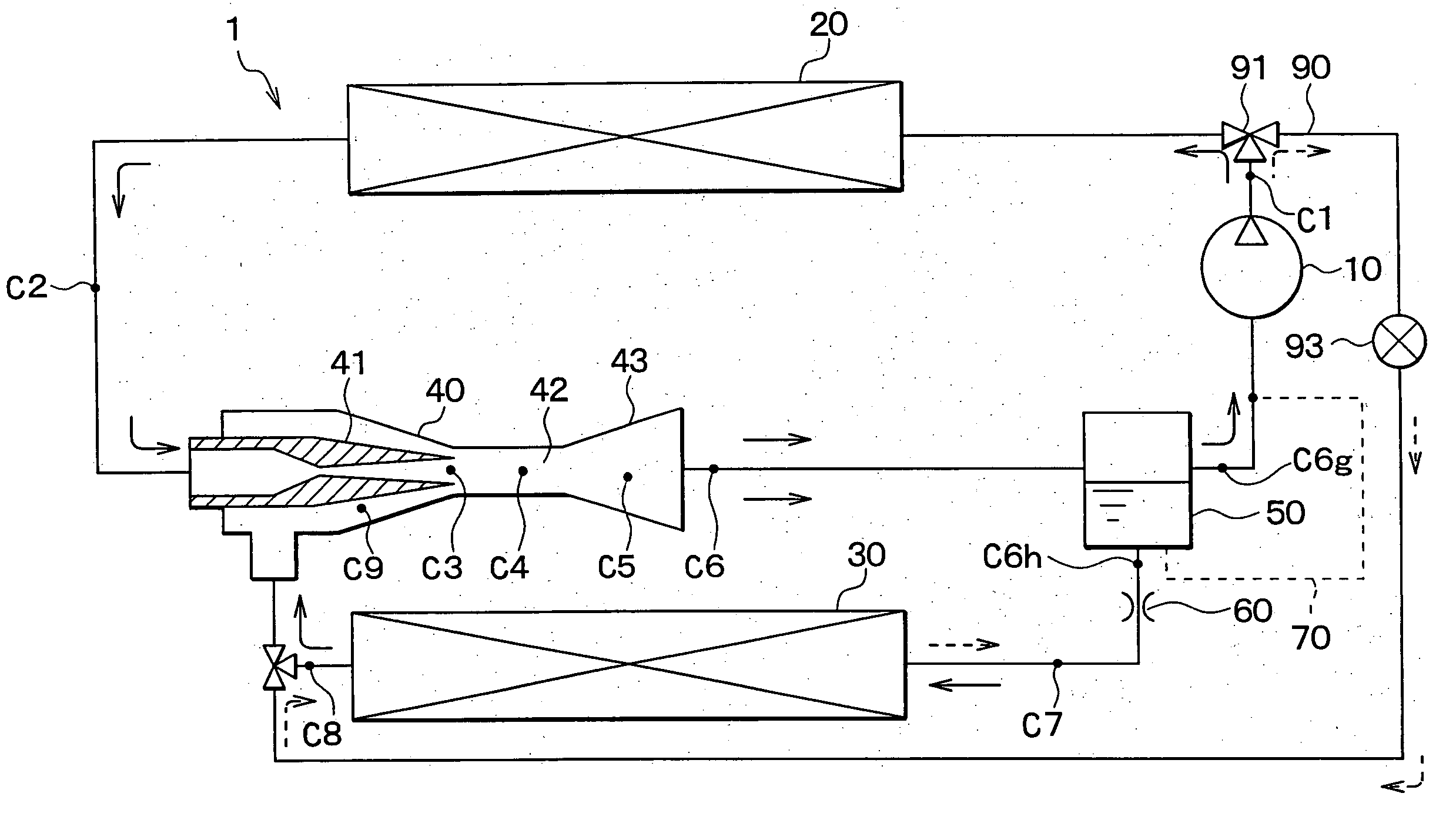
[0066] The third embodiment of the present invention will be now described with reference to FIGS. 9-12. In the third embodiment, as shown in FIGS. 9-12, a bypass passage 90, into which high-pressure refrigerant flows while bypassing at least the nozzle 41, is directly connected to the evaporator 30. In the third embodiment, the second oil return passage 80 described in the above first and second embodiments is not provided. A three-way valve 91 is provided at a branch point of the bypass passage 90 and a high-pressure refrigerant passage coupled to the nozzle 41 of the ejector 40. The three-way valve 91 is disposed to switch a refrigerant flow into the bypass passage 90. An expansion valve 93 is provided in the bypass passage 90, and decompresses and expands refrigerant in the bypass passage 90. When the pressure increasing value .DELTA.P in the ejector 40 is equal to or lower than a predetermined pressure, or when the ejector efficiency .eta.e is equal to ...
PUM
 Abstract
Description
Claims
Application Information
 - R&D
- Intellectual Property
- Life Sciences
- Materials
- Tech Scout
- Unparalleled Data Quality
- Higher Quality Content
- 60% Fewer Hallucinations
Browse by: Latest US Patents, China's latest patents, Technical Efficacy Thesaurus, Application Domain, Technology Topic, Popular Technical Reports.
© 2025 PatSnap. All rights reserved.Legal|Privacy policy|Modern Slavery Act Transparency Statement|Sitemap|About US| Contact US: help@patsnap.com


