Hand power tool with a pneumatic striking mechanism

Inactive Publication Date: 2004-01-29
ROBERT BOSCH GMBH
View PDF9 Cites 10 Cited by
  • Summary
  • Abstract
  • Description
  • Claims
  • Application Information

AI Technical Summary

Benefits of technology

[0003] The object stated above is attained with the characteristics of claim 1, in that the covering for the at least one control opening in the hammer barrel comprises an elastomer. With this kind of covering, a sealing gap that is deleterious to the generation of the negative pressure in the hammer barrel is avoided, and the efficiency of the striking mechanism is thus increased. Moreover, this kind of covering comprising elastomer has advantages in terms of production over a steel control sleeve.[0004] Advantageous embodiments and refinements of the invention are defined by the dependent claims. The hammer barrel can be supported displaceably in the direction of its longitudinal axis in the power tool housing. Then the covering is advantageously disposed in the power tool housing, nondisplaceably in the axial direction, in such a way that upon an axial displacement into the striking position, the hammer barrel moves with its at least one control opening to beneath the covering.[0005] In another advantageous feature, a retaining means, supported displaceably in the axial direction, for the covering is disposed in the power tool housing, and means are present which at the transition from the idle position to the striking position displace the retaining means along with the covering axially, so that the covering comes to rest above the at least one control opening in the hammer barrel. Advantageously, the means comprise a snap head die, which is supported in the hammer barrel and is displaced against a machining point by a tool introduced into the hammer barrel displaces against a machining point when the tool is pressed upon, and which has a stop that transmits the axial motion of the snap head die to the retaining means of the covering. The stop can be a disk, which is placed on the snap head die and which protrudes with one or more arms through an opening in the hammer barrel as far as the retaining means surrounding the hammer barrel.[0006] It is expedient that the retaining means for the covering is embodied such that it enables play of the covering in the radial direction relative to the hammer barrel.[0007] Preferably, the covering is a control sleeve surrounding the hammer barrel.

Problems solved by technology

With this kind of control sleeve, the control opening can be closed only inadequately, since there is always a certain sealing gap between the steel control sleeve and the hammer barrel.
The efficiency of the striking mechanism suffers as a result.

Method used


Image

  • Hand power tool with a pneumatic striking mechanism
  • Hand power tool with a pneumatic striking mechanism
  • Hand power tool with a pneumatic striking mechanism

Examples


Embodiment Construction

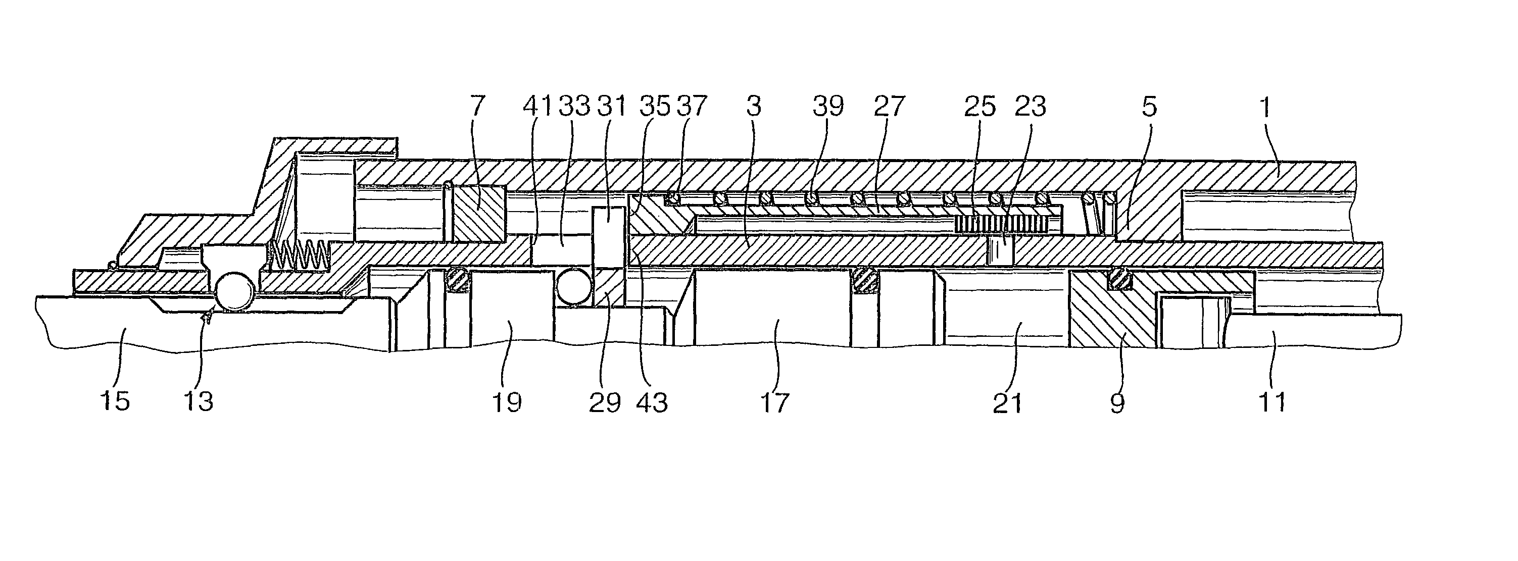
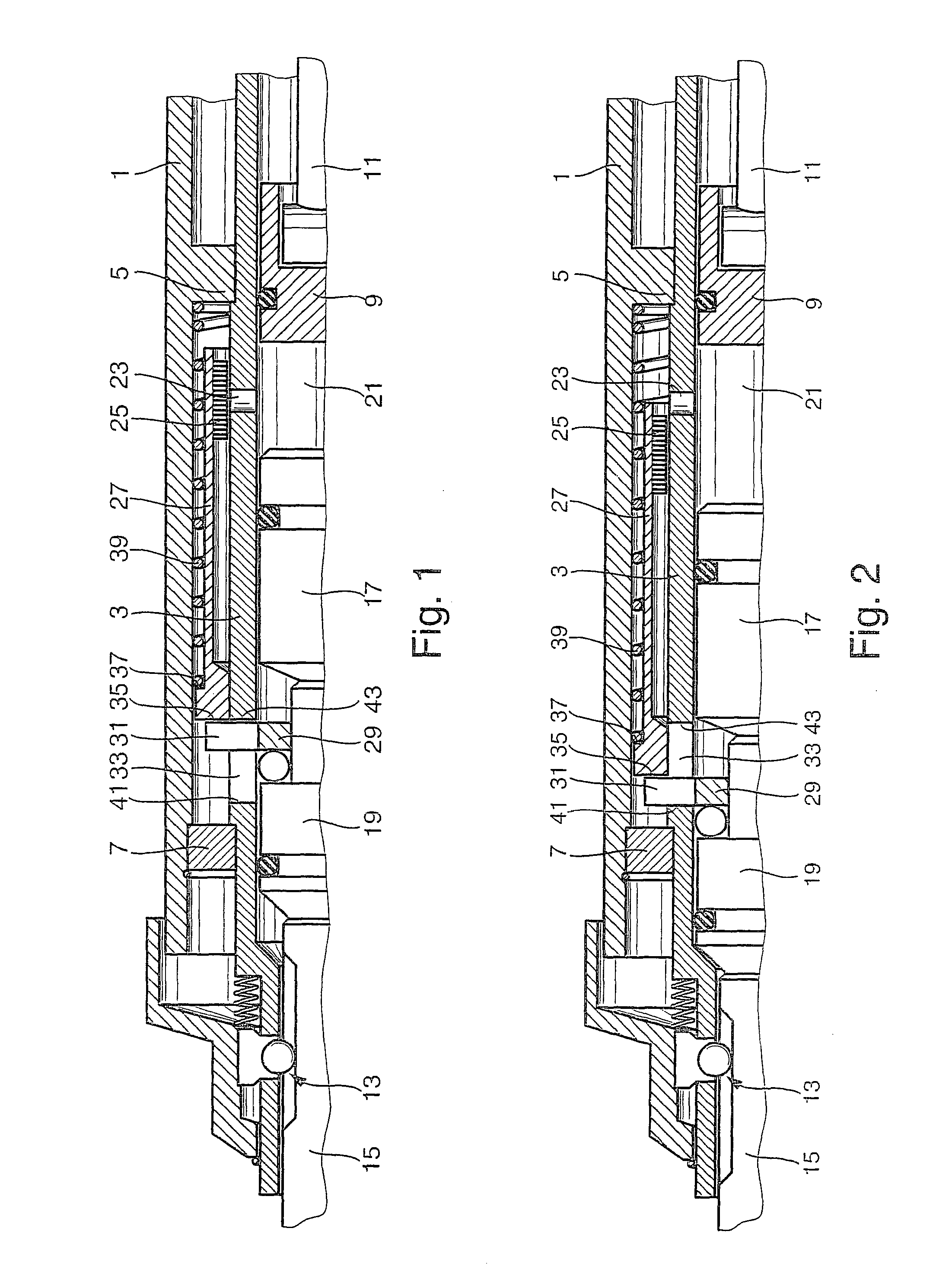
[0012] FIGS. 1 and 2 show a fragmentary longitudinal section through the striking mechanism of a drill hammer; the striking mechanism is shown in FIG. 1 in the striking position and in FIG. 2 in the idle position. The striking mechanism of this drill hammer has the following construction:

[0013] A hammer barrel 3 is rotatably supported in the power tool housing 1. Two bearing points 5 and 7 are located on the inner wall of the power tool housing 1; the bearing point 5, for instance, is an annular collar protruding integrally inward from the power tool housing 1, and the bearing point 7 is a bearing ring retained in the power tool housing 1. With its bearing points 5 and 7, the hammer barrel 3 forms a stop, so that it is not displaceable in the direction of its longitudinal axis.

[0014] A piston 9 is accommodated in the hammer barrel 3 and can be driven to reciprocate axially via a connecting rod 11. On its end remote from the piston 9, the hammer barrel 3 is provided with a tool recep...


PUM

PropertyMeasurementUnit
Efficiencyaaaaaaaaaa

Abstract

The striking mechanism has a hammer barrel (3), which has at least one control opening (23) through which, in an idle position, the air can escape from the hammer barrel (3), and which in a striking position is closed by a covering (25) that prevents the escape of air. To achieve the greatest possible sealing off of the at least one control opening (23) and thus high efficiency of the striking mechanism, the covering (25) is molded from an elastomer.

Description

PRIOR ART[0001] The present invention relates to a hand power tool--preferably a drill hammer or jackhammer--with a pneumatic striking mechanism that has a hammer barrel which has at least one control opening, through which, in an idle position, air can escape from the hammer barrel and which is closed, in a striking position, by a covering preventing the escape of air.[0002] A hand power tool of this kind with a pneumatic striking mechanism is known, for instance from German Patent Disclosure DE 197 24 531 A1. In the drill hammer or jackhammer described in this reference, an axially displaceably supported hammer barrel is disposed in the power tool housing. An axially reciprocating piston is accommodated in the hammer barrel and is coupled with a striker via an air cushion. A restoring spring, with a restoring force, urges the hammer barrel in the direction of an outset position, in which the air cushion space in the hammer barrel is ventilated via a control opening, so that the st...

Claims


Application Information

Patent Timeline
IPC IPC(8): B23B45/16B25D11/00
CPCB25D11/005B25D2250/131B25D2250/035B25D2222/57
Inventor MUELLER, FRANKMEIXNER, GERHARD
Owner ROBERT BOSCH GMBH
Why Eureka
Try Eureka