Antenna of small dimensions

a technology of small dimensions and antennas, applied in the direction of antenna supports/mountings, electrical devices, radiating element structural forms, etc., can solve the problems of substantially reduced passband of antennas and practicable unusability

Inactive Publication Date: 2004-01-29
AMPHENOL SOCAPEX
View PDF3 Cites 100 Cited by
  • Summary
  • Abstract
  • Description
  • Claims
  • Application Information

AI Technical Summary

Benefits of technology

[0018] Preferably, the slot or at least one of said slots is open. Under such circumstances, radiation from the slot is avoided and the operation of the antenna is greatly improved.

Problems solved by technology

Unfortunately, it has been found that if attempts are made to reduce the thickness of a PiFa antenna so as to bring it down to less than 5 mm, for example, then the passband of the antenna is considerably reduced, thus making it practically unusable.

Method used


Image

  • Antenna of small dimensions
  • Antenna of small dimensions
  • Antenna of small dimensions

Examples


Embodiment Construction

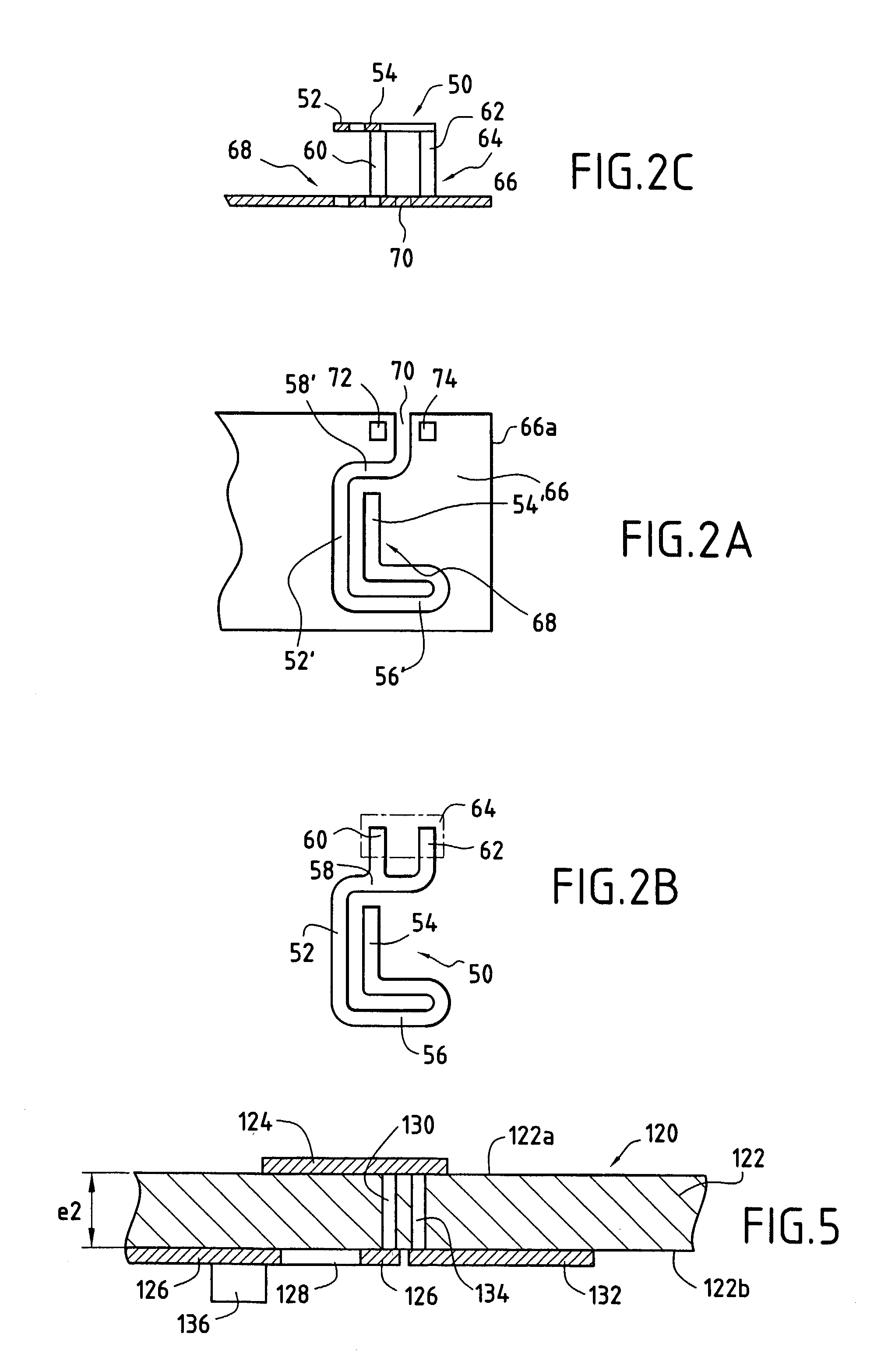
[0049] With reference to FIGS. 2A to 2C, there follows a description of a first embodiment of an antenna in accordance with the first aspect of the invention.

[0050] In this particular embodiment, as can be seen in FIG. 2B, the radiating element 50 is in the form of a plate and comprises two parallel main portions 52 and 54 that are united at one end by a loop 56 and that are extended at the opposite end of the rectilinear portion 52 by a branch 58. The shape of the radiating element is defined by the operating frequency(ies) of the antenna and by the desired impedance. The branch 58 is extended by two connection tabs 60 and 62 respectively for the antenna feed and for the short circuit, which tabs are fixed to a dual connection element 64. Other shapes could be used for the radiating element.

[0051] FIG. 2A shows a conductive surface 66 with its slot 68 whose outline is close to that of the radiating element 50, but is not necessarily identical thereto. The slot is constituted by slo...


PUM


Abstract

The invention relates to an antenna of small dimensions. According to an embodiment, the antenna comprises: a radiating element in the form of a plate; an antenna feed connected to the radiating element; a conductive surface substantially parallel to the radiating element and placed at a distance e from the element, the conductive surface being provided with at least one slot facing the radiating element; and a conductive connection between the conductive surface and the radiating element.

Description

[0001] The present invention relates to an antenna of small dimensions for use particularly but not exclusively in a portable radiotelephone.[0002] In portable radiotelephones, it is known to use helically-shaped antennas that are usually mounted outside the housing of the radiotelephone. Such antennas can be relatively small in size but they are located outside the housing in order to be associated with a ground plane that is located inside the housing of the radiotelephone.[0003] A present trend in the manufacture of radio-telephones is to eliminate any external antenna and to place the antenna inside the housing. Another trend is also towards reducing the dimensions of the radio-telephone, or at least to integrating the largest possible number of components in a radiotelephone of given outside dimensions.[0004] As a result, it is advantageous in terms of radio-telephone design for the antenna to satisfy two conditions: it should be internal, and it should be of dimensions that ar...

Claims


Application Information

Patent Timeline
Patent Type & Authority Applications(United States)
IPC IPC(8): H01Q1/24H01Q1/36
CPCH01Q1/243H01Q1/362H01Q1/36
Inventor ANNABI, AYOUBVINCENT, ROLANDLECLERC, DANIEL
Owner AMPHENOL SOCAPEX
Why Eureka
Try Eureka