Micro-mirror with rotor structure

a technology of rotor structure and mirror, which is applied in the direction of generator/motor, snap-action arrangement, instruments, etc., can solve the problems of low yield and reliability, integration and reliability problems, and the difficulty of achieving high-quality mirror surfaces

Inactive Publication Date: 2004-01-29
HEWLETT PACKARD DEV CO LP
View PDF8 Cites 82 Cited by
  • Summary
  • Abstract
  • Description
  • Claims
  • Application Information

AI Technical Summary

Problems solved by technology

These known approaches can involve complex position control systems, and utilize fragile structures which can provide low yield and reliability.
High voltages of 200 V or more to generate enough force to rotate the mirror can lead to integration difficulties and reliability problems.
High quality mirror surfaces can be difficult to achieve due to thinness of the mirror plate and stresses applied during the fabrication processes.
The inkjet approach is relatively slow due to its thermal actuation, and requires relatively large amounts of die space to achieve N.times.N cross connects.

Method used


Image

  • Micro-mirror with rotor structure
  • Micro-mirror with rotor structure
  • Micro-mirror with rotor structure

Examples


Embodiment Construction

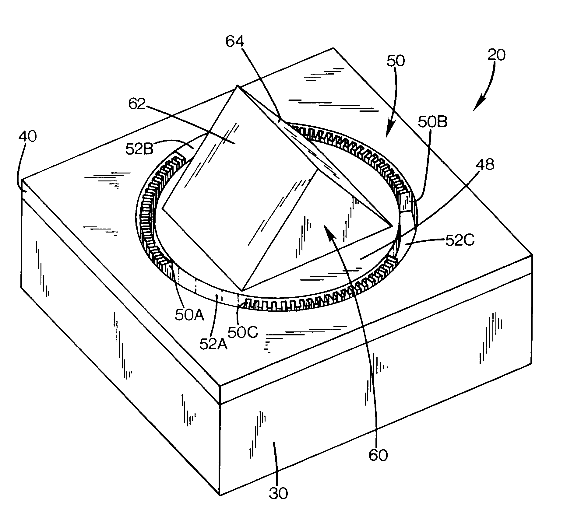
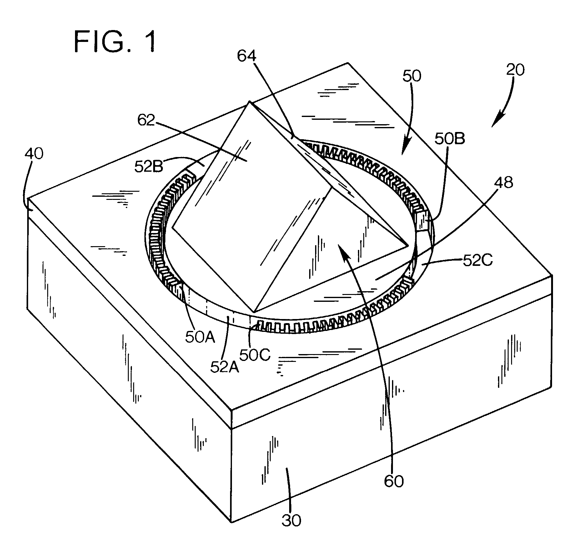
[0017] A micro mover generates rotary step motion with a limited rotation angle (10 to 15 degrees in one exemplary embodiment). A bulk silicon micromachined mirror is built on top of the motor, in one exemplary embodiment using wet etch techniques, although other techniques can also be employed. This device can be used for deflecting the light to different location. The micro mover can be used for scanning mirror and display applications.

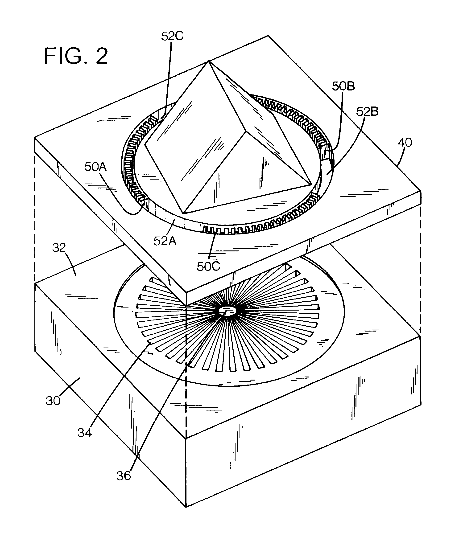
[0018] An embodiment of a micro mover structure is described which includes radial, electrostatically actuated stator and rotor electrodes to generate electrostatic rotary force and stepping motion on the rotor. In one exemplary embodiment, the step motion of the rotor can be actuated by changing the voltage on one of the sets of electrodes from high to low, or low to high, i.e. a digital control scheme. The micro mover structure includes suspended flexures on the rotor. A silicon micromachined mirror is fabricated on the rotor. The electrodes gener...


PUM


Abstract

A micro-mirror device includes a stator structure having a set of radial stator electrodes, a rotor structure having a set of radial rotor electrodes, a mirror mounted on the rotor structure, and a flexure structure suspending the rotor structure relative to the stator structure. 100111168 1

Description

BACKGROUND OF THE DISCLOSURE[0001] Micro-actuators have been formed on insulators or other substrates using micro-electronic techniques such as photolithography, vapor deposition and etching. Such micro-actuators are often referred to as micro-electromechanical system (MEMS) devices.[0002] Optical switching technologies are being developed for optical communication and display systems. Known MEMS (microelectromechanical switch) approaches include electrostatic, magnetic, piezoelectric and thermal mechanical MEMS devices, which employ thin mirrors to reflect a light beam. These known approaches can involve complex position control systems, and utilize fragile structures which can provide low yield and reliability. High voltages of 200 V or more to generate enough force to rotate the mirror can lead to integration difficulties and reliability problems. High quality mirror surfaces can be difficult to achieve due to thinness of the mirror plate and stresses applied during the fabricati...

Claims


Application Information

Patent Timeline
Patent Type & Authority Applications(United States)
IPC IPC(8): B81B5/00G02B6/35G02B26/08
CPCG02B6/352G02B6/3556Y10S359/904G02B6/3584G02B26/0841G02B6/357B81B3/0062B81B2201/047B81B2203/0109B81B2203/056
Inventor YANG, XIAOFENG
Owner HEWLETT PACKARD DEV CO LP
Why Eureka
Try Eureka