Device for illuminating indoors by using sunlight

A technology of sunlight and direct sunlight, applied in the field of solar energy utilization, can solve the problems of increasing cooling energy consumption, inability to save energy, and no way to continue to track the position of the sun, so as to achieve the effect of improving energy utilization and equipment utilization efficiency

Inactive Publication Date: 2003-10-08
谭洪源
View PDF2 Cites 36 Cited by
  • Summary
  • Abstract
  • Description
  • Claims
  • Application Information

AI Technical Summary

Problems solved by technology

The main disadvantage of this device is that it is only suitable for rooms directly below the roof of the building; in the morning and evening, the intensity of sunlight is relatively small, because the angle between the light receiving surface of the device and the direct sunlight is relatively large. , so there is very little light that can be introduced into the room at these moments, and these moments are the most insufficient lighting in the building, mainly because the lighting surface of the device only rotates in one-dimensional direction, and the effective area of ​​the lighting surface cannot be maximized.
Compared with clock calculation control, this control method is more accurate, but it also has the following disadvantages: if the sky is covered by clouds, the control system cannot get the input signal of the sensor, and there will be no way to continuously track the position of the sun
In cloudy weather conditions, the brightness of the edge of the cloud may become the strongest light. At this time, the system will not track the position of the sun. If the number of sensors installe

Method used


Image

  • Device for illuminating indoors by using sunlight
  • Device for illuminating indoors by using sunlight
  • Device for illuminating indoors by using sunlight

Examples


Embodiment 1

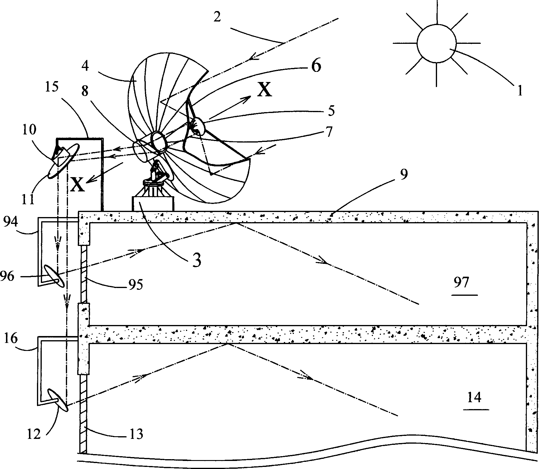
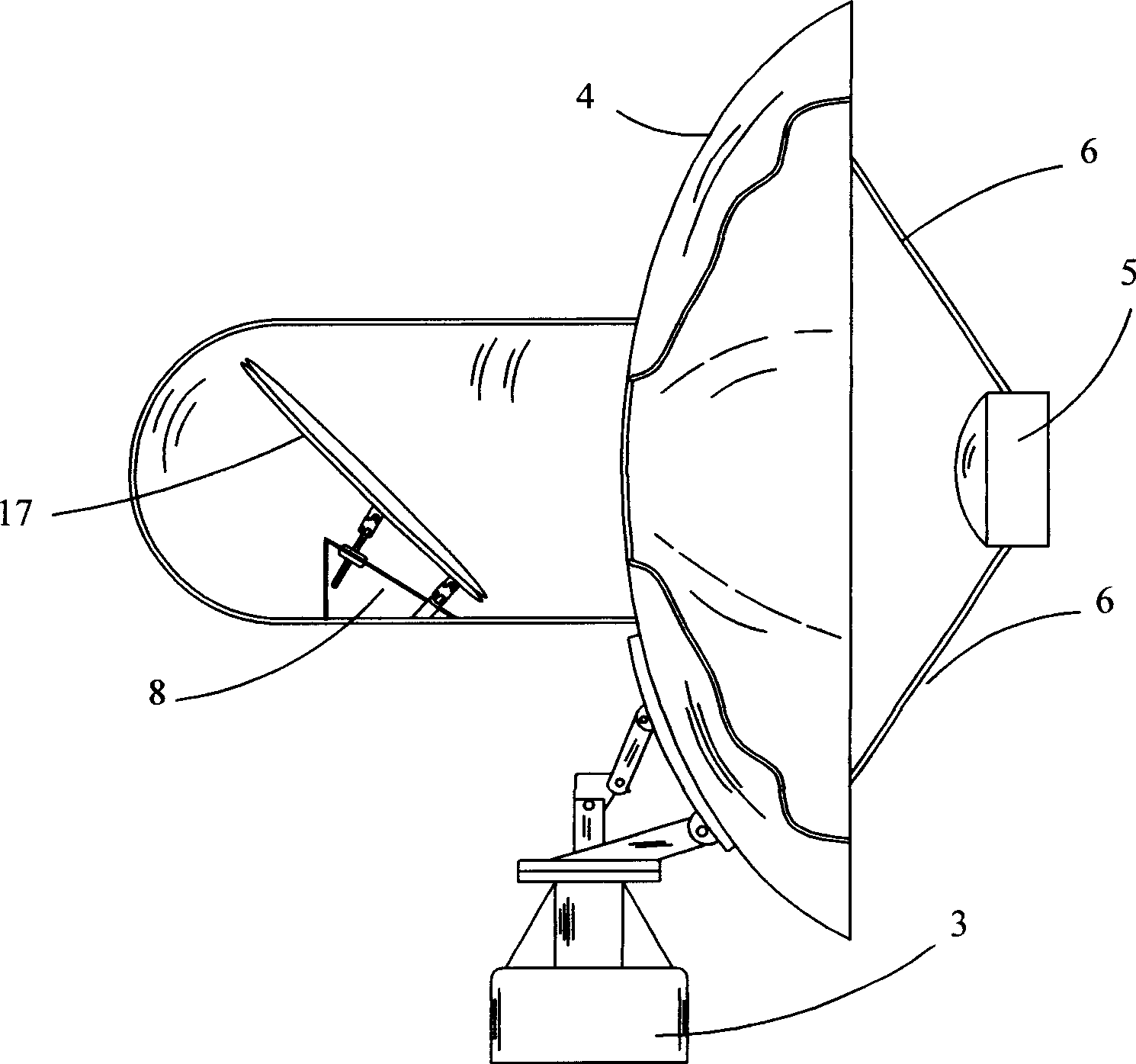
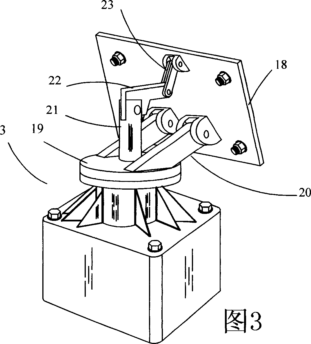
[0053] exist figure 1 , figure 2 Among them, the two-dimensional tracker 3 of the rear channel type concentrating daylighting device is fixedly installed on the top of the building 9, the parabolic concentrator 4 is installed on the two-dimensional tracker 3, and the secondary reflector 5 is fixed on the top of the building 9 by three support rods 6 The focal point of the parabolic concentrator 4, the two-dimensionally adjusted three-time reflector 8 and the secondary reflector 5 are all on the optical axis X-X of the parabolic concentrator 4, and the two-dimensionally adjusted four-time reflector is fixed on the top of the building 9 by a support rod 15 The edge of five secondary reflectors 12,96 is respectively fixed on the window 13,95 outside of indoor 14,97 that needs daylighting by support bar 16,94. The two-dimensional tracker 3 drives the parabolic concentrator 4 to face the sun 1 all the time, so that the direct light 2 of the sun 1 is parallel to the optical axis X...

Embodiment 2

[0067] The front channel type concentrating daylighting device of this embodiment is designed for the floors closest to the top of the building.

[0068] exist Figure 11 Among them, the front channel type concentrating daylighting device and the rear channel type concentrating daylighting device 77 are installed on the top of the building 9 together.

[0069] This example Figure 12 , 13 As shown in and 14, the substantive structure of the front channel type concentrating daylighting device is basically the same as that of Embodiment 1, and its components include a parabolic concentrator 71, a two-dimensional tracker 3, an optical bench cone 72, an optical path channel 73 and a photosensitive sensor 39a ~ 39d, encoder and central control system. The parabolic concentrator 71 is installed on the two-dimensional tracker 3, the optical frustum cone 72 is fixed on the optical axis X-X of the parabolic concentrator 71 by three support rods 6, and the optical path channel 73 run...

Embodiment 3

[0072] exist Figure 15In this embodiment, the Fresnel lens is used to replace the parabolic concentrator of the back channel type concentrating daylighting device as the light converging element. The two-dimensional tracker 3 is installed on the base plate 92, the Fresnel lens group 83 is fixedly installed on the base plate 92 by the bracket 93, the condenser lens 84 is installed on the focus of the Fresnel lens 83, and the mirror 86 is installed on the In the transparent protective cover 85, the solar photovoltaic cell panel 87 is installed at the bottom of the transparent protective cover 85, the secondary reflector 88 is fixed on the base plate 92, and the two-dimensionally adjustable tertiary reflector 90 is connected with the base plate 92 through three support rods 91 . The sun's direct light rays 98 are converged by the Fresnel lens 83 to the condenser lens 84, corrected into parallel light by the condenser lens 84, reflected by the reflector 86 to the secondary refle...


PUM


Abstract

This invention discloses a sunlight collecting device composed of a two-dimensional tracer, optical collector, an indirect reflector, two-dimensional adjust reflector, reflecting mirror mounted outside of a window of a place necessary for collecting light, solar energy photo-voltaic battery, photosensitive sensor, coder and central controller. After the optical collector collects direct sunlight,the indirect reflector corrects it to be parallel light to be reflected to a definite place and reflected indoor by the reflection mirror. The device motion is controlled by the central controller and a coder is mounted on the operating motor to record the motor operation angle.

Description

technical field [0001] The invention relates to a sunlight lighting device that conducts sunlight indoors, especially a device that can automatically track the sun, gather direct sunlight and filter out some ultraviolet rays and infrared rays, and then transmit it to the room for lighting, which belongs to the solar energy utilization technology field. Background technique [0002] Using sunlight indoors as much as possible can not only save a lot of energy, but also improve the quality of the indoor environment. Along with the history of human beings building houses, daylighting has always been an important factor that must be considered in the design and construction of the architectural field. The angle of sunlight irradiation changes with time, and the sunlight irradiation situation will change in different seasons and different climates. Therefore, for a building, the amount of sunlight and the angle of illumination are different at differen...

Claims


Application Information

Patent Timeline
IPC IPC(8): F21S11/00
Inventor 谭洪源
Owner 谭洪源
Why Eureka
Try Eureka