Tunable chromatic dispersion compensator

Active Publication Date: 2004-01-29
TERAXION
View PDF15 Cites 13 Cited by
  • Summary
  • Abstract
  • Description
  • Claims
  • Application Information

AI Technical Summary

Problems solved by technology

On the other hand, a non uniform heating, such as to produce a thermal gradient along the waveguide axis in the region of the grating, induces a chirp in the grating, or modifies an existing one.
These devices however imply gluing the fiber to a metallic block along its entire length, which in practice is a technologically challenging operation.
F

Method used


Image

  • Tunable chromatic dispersion compensator
  • Tunable chromatic dispersion compensator
  • Tunable chromatic dispersion compensator

Examples


Embodiment Construction

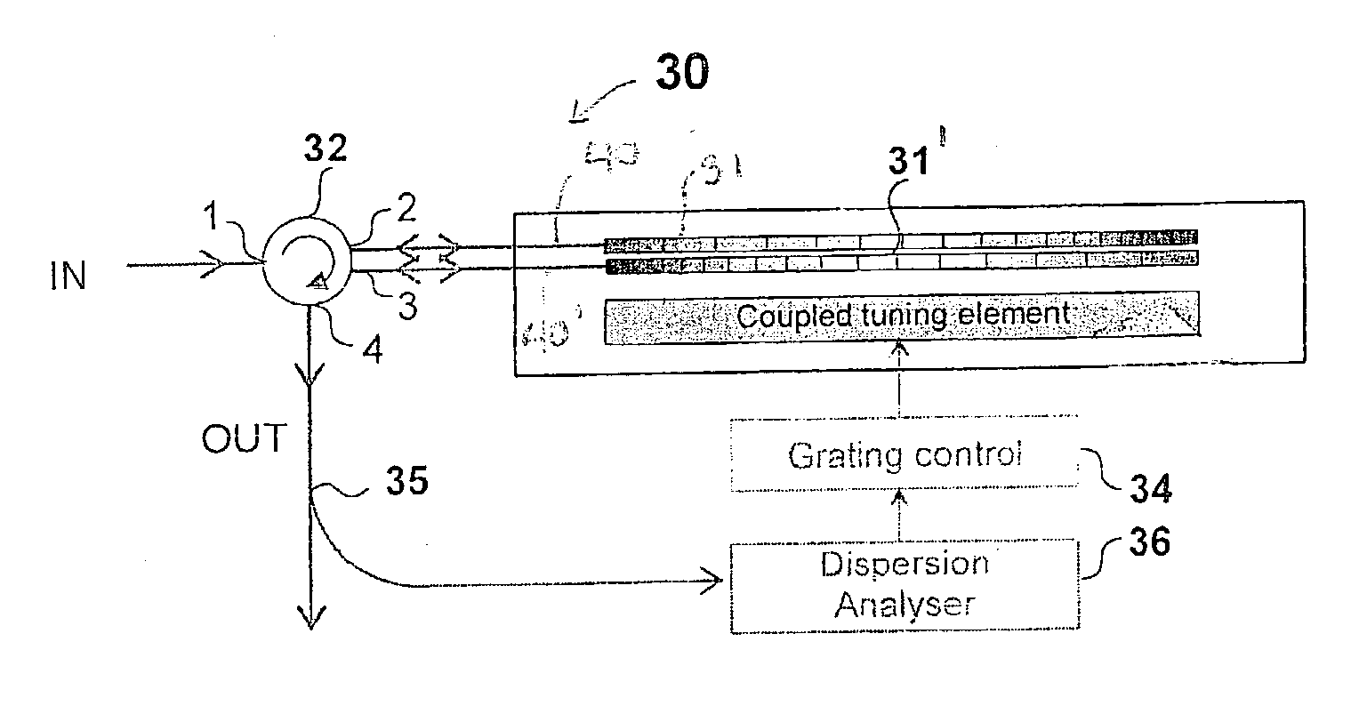
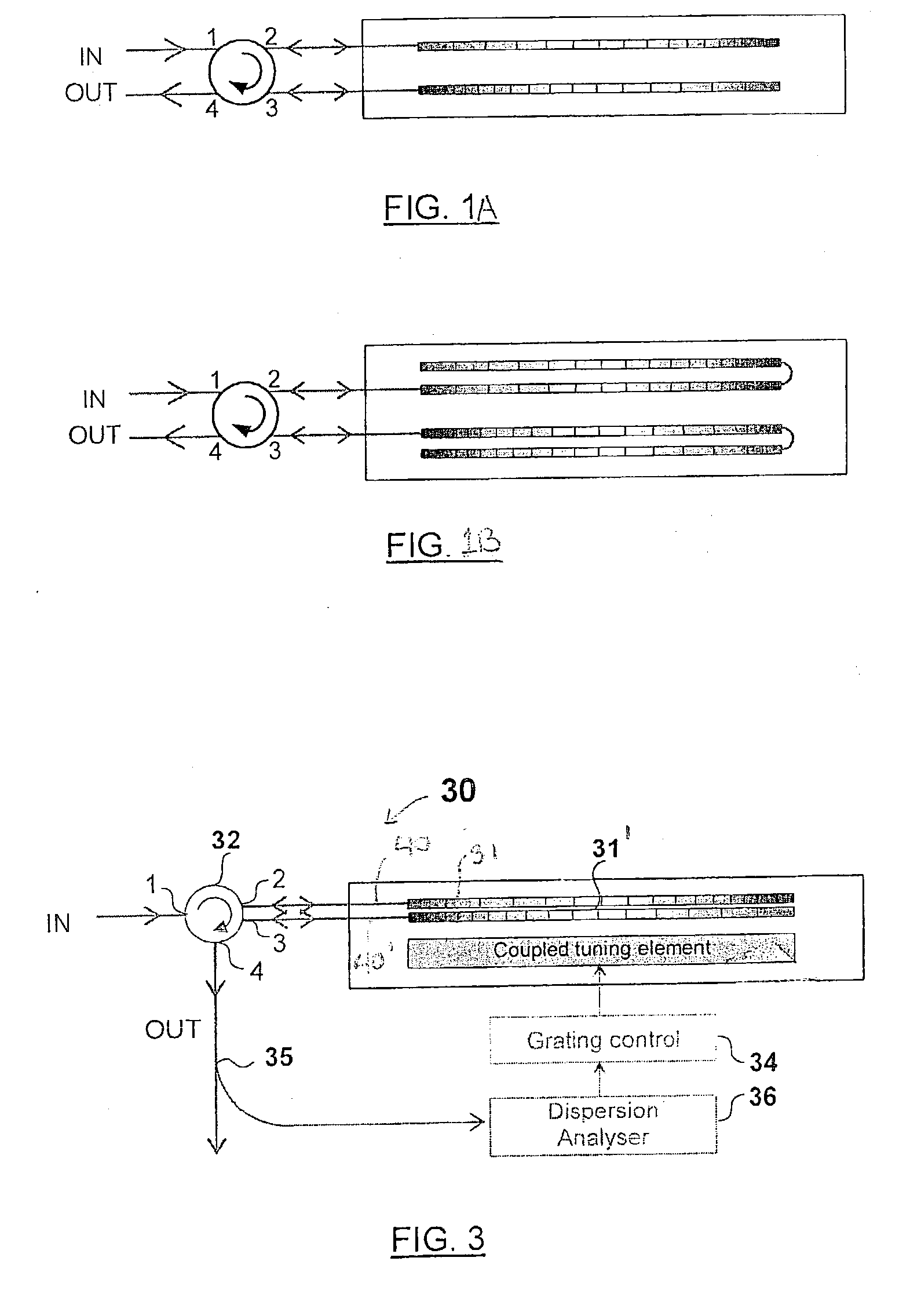
[0032] The present invention generally provides for the versatile and practical tuning of the dispersion compensation provided by a compensator to fit real-life situations encountered in optical telecommunication systems.

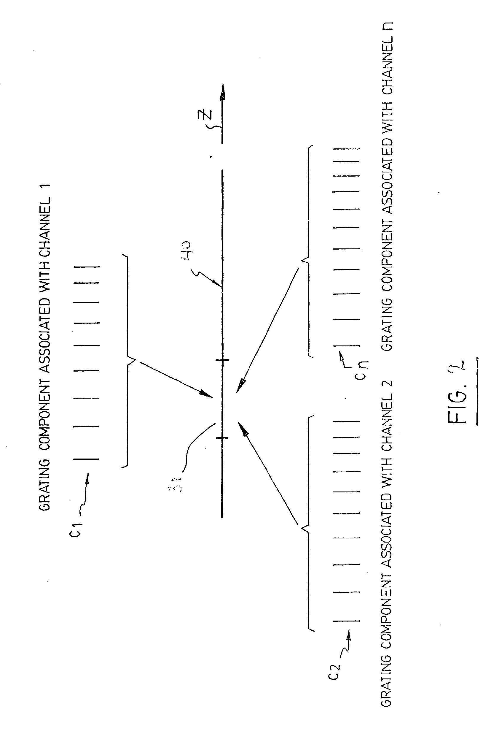
[0033] Referring to FIG. 3, there is shown an exemplary embodiment of a tunable dispersion compensator 30 the compensation of chromatic dispersion in a light signal according to the present invention. Depending on the embodiment the light signal may include a single or multiple WDM channels. The compensator 30 includes a plurality of waveguide segments 40 each provided with an optical structure 31. Each optical structure 31 is preferably one or a combination of chirped Bragg gratings, and as such therefore a characteristic dispersion profile representing the effect it will have on the light signal it reflects. Different examples of appropriate optical structures 31 will be given below.

[0034] The compensator 30 further includes an optical coupling arrangement coupled...


PUM


Abstract

A tunable dispersion compensator for the compensation of the chromatic dispersion experienced by a single-channel or multi-channel light signal. The compensator includes a plurality of optical structures such as chirped Bragg gratings or combinations thereof, each having a characteristic dispersion profile. An optical coupling arrangement successively propagates the light signal in each of these structures, so that it accumulates the dispersion compensation effect of each. A tuning device jointly tunes the dispersion profile of each optical structure by applying a same tuning force thereto, preferably a temperature gradient.

Description

[0001] The present invention relates to the compensation of chromatic dispersion occurring in waveguides such as optical fibers. More specifically, the invention concerns a multi-grating based tunable dispersion compensator.[0002] In optical telecommunication systems, one of the many difficulties encountered is the chromatic dispersion of light signals propagating over long distances in optical media such as optical fibers. Chromatic dispersion causes light pulses to spread out as they travel along an optical fiber. It occurs because the different spectral components at different wavelengths in a pulse travel at slightly different speeds. An optical pulse, which comprises different optical spectral components, therefore, can be broadened or distorted in shape after propagation through a distance in such a dispersive optical medium. This dispersion effect can be undesirable and even adverse for certain applications such as optical communication systems where information is encoded, p...

Claims


Application Information

Patent Timeline
IPC IPC(8): H04B10/2519G06F17/30
CPCG02B6/02195G02B6/2932H04B10/2519G02B6/29395G06F17/30864G02B6/29394G06F16/951
Inventor LELIEVRE, SYLVIANELACHANCE, RICHARD L.PAINCHAUD, YVES
Owner TERAXION
Why Eureka
Try Eureka