
Low voltage pyrotechnic igniter assembly

a low-voltage, pyrotechnic technology, applied in the direction of electric fuzes, ammunition fuzes, weapons, etc., can solve the problems of unsuitable consumer-class fireworks, unnecessarily laborious and time-consuming firework preparation, and high system cos

Inactive Publication Date: 2004-02-05
BAILEY SAMUEL WALTERS +1
View PDF4 Cites 7 Cited by
  • Summary
  • Abstract
  • Description
  • Claims
  • Application Information

AI Technical Summary

Problems solved by technology

These systems are typically expensive and are therefore used principally by professional pyrotechnicians.
The above mentioned capacitive discharge igniter is not suitable for use with consumer class fireworks from the standpoint of practical application, safety and expense.
For example, the firework preparation is unnecessarily laborious and time consuming for a small consumer class firework display.
Preparing the firework by drilling into it is a dangerous activity as is the shipping and handling of the flammable and toxic chemicals, involved with the electric match.
Additionally, these ignition systems are prohibitively expensive and complicated for typical consumer use.
Although the previous art of fuse igniters such as U.S. Pat. No. 2,114,176 to H. C. Christ (1938) shows an igniter utilizing resistance wire, there is no means to readily replace the wire were it defective.
It is common knowledge within the industry that when a fuse is consumed there is considerable residue of a waxy deposit that can coat the resistive element rendering it useless for repeated ignitions.
However, consumer class fireworks typically have a fuse length of only a few inches at best, so that using devices such as that of Christ or Frye would place the user in the dangerous area of detonation.
These devices are difficult and sometimes impossible to use in breezy or damp weather and users can easily ignite the fuse closer to the firework than intended, substantially shortening the time to detonation.
More importantly, they all require the user to be dangerously close to the firework's point of detonation.

Method used


Image

  • Low voltage pyrotechnic igniter assembly
  • Low voltage pyrotechnic igniter assembly
  • Low voltage pyrotechnic igniter assembly

Examples


Embodiment Construction

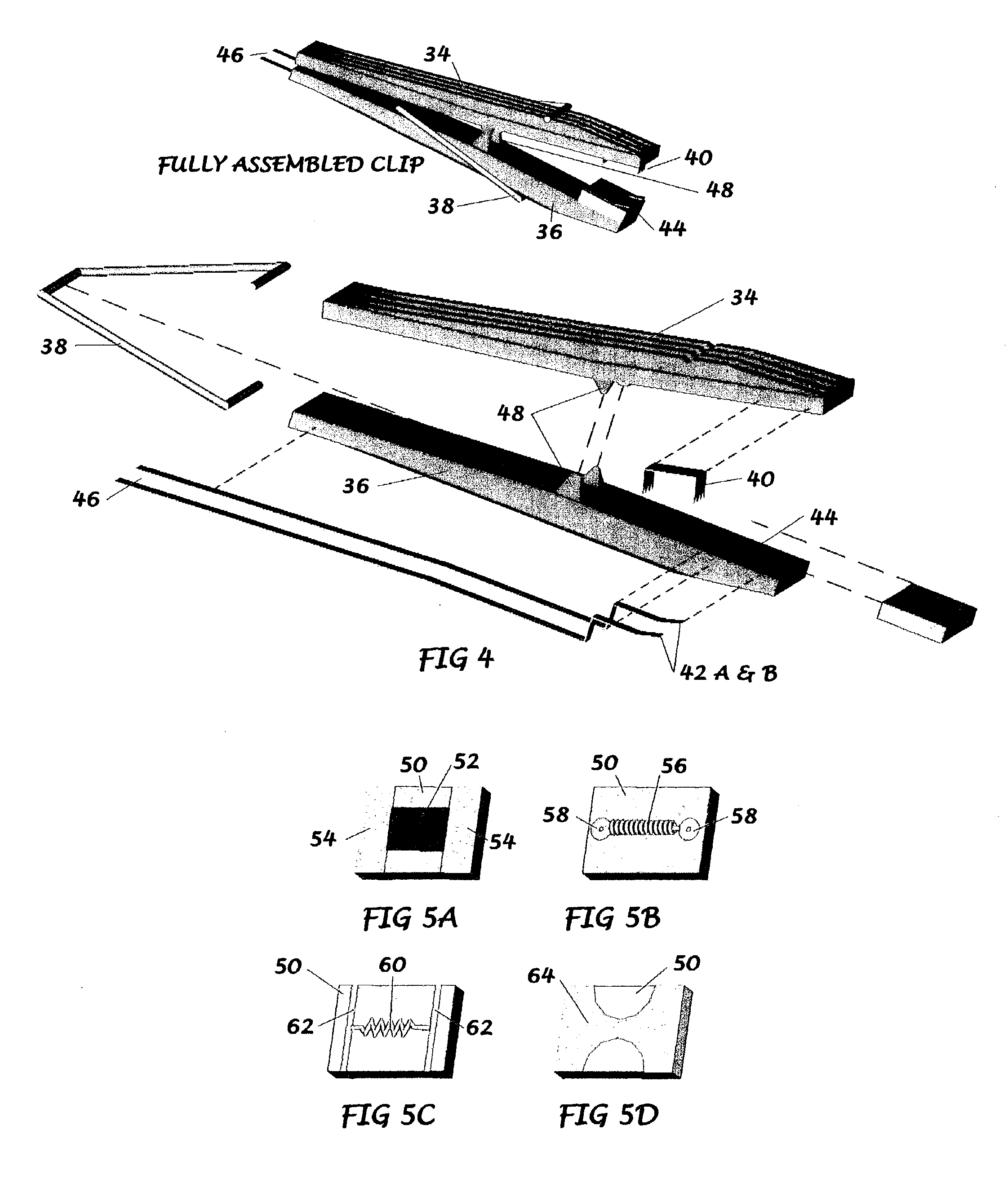
[0058] Nothing in these figures is intended to suggest a single best embodiment or that other embodiments are not acceptable and workable. Other enhancements to the invention of this application are noted in the claims section but may not be identified here. Variations include but are not limited to; a power control unit capable of providing power to more than one clip / igniter element; the addition of a utility light on the housing or clip; and the addition of various lighting and / or sound generating components for use as decoration or entertainment.

[0059] FIG. 1

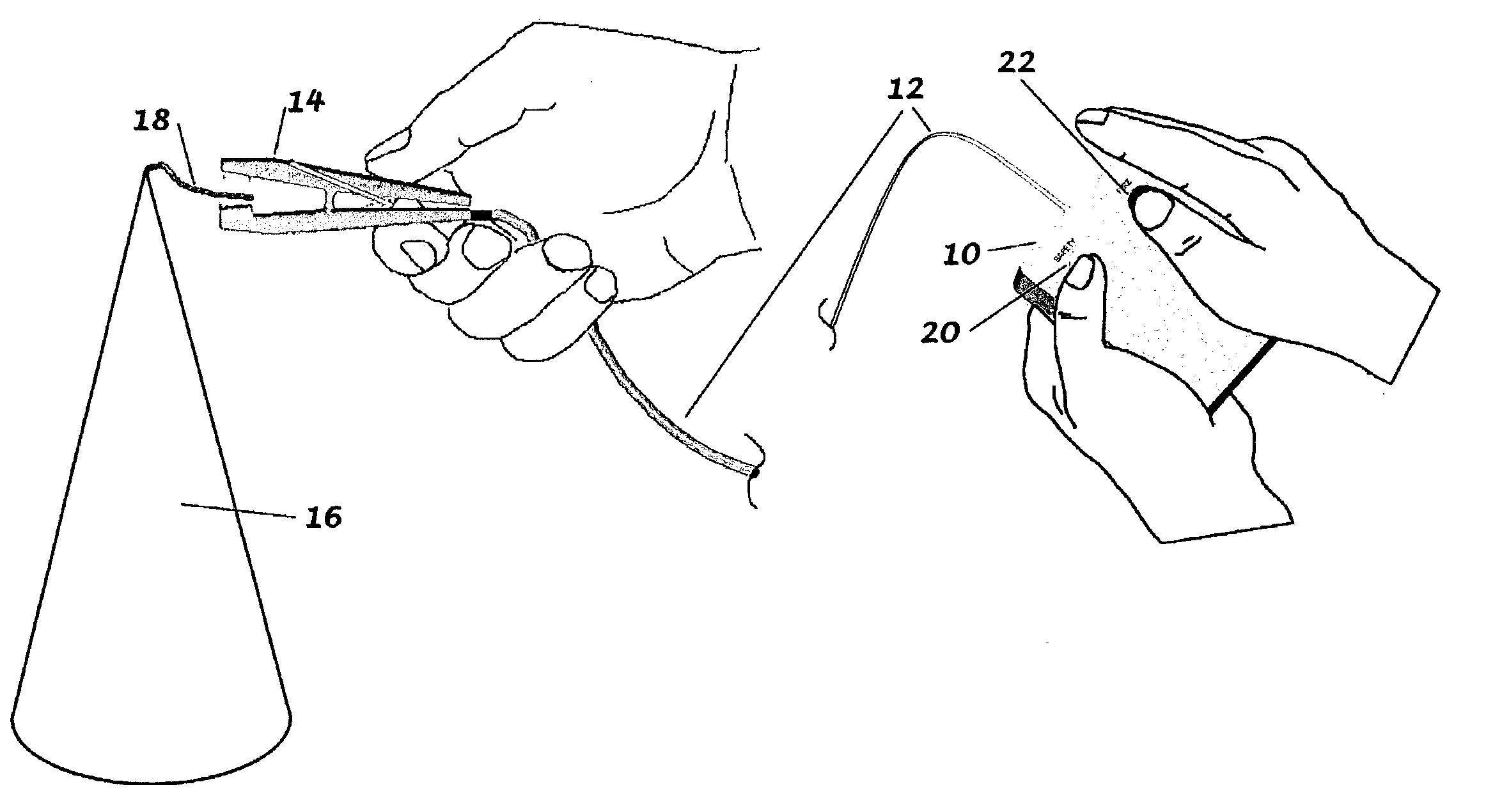
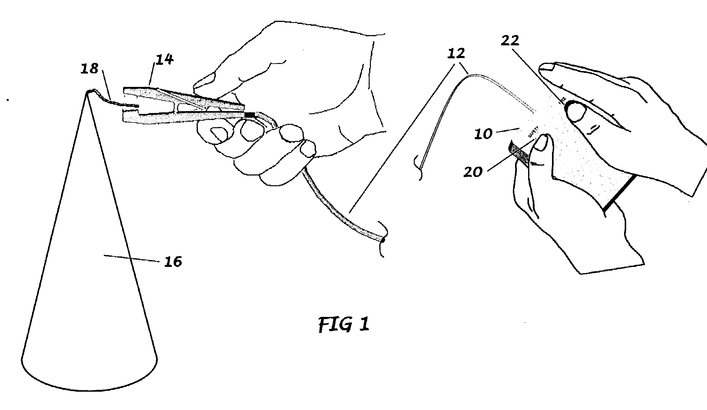
[0060] A preferred embodiment of the entire igniter assembly of the present invention is illustrated in FIG. 1. The user holds the power control unit 10. When the safety switch 20 and the ignition switch 22 are simultaneously depressed power is conducted through the two-conductor wire 12 to the clip 14 where the firework 16 is detonated.

[0061] FIG. 2

[0062] The method of attaching the clip to the firework fuse is indicated wh...


PUM


Abstract

The electric pyrotechnic igniter of the present invention comprises a controlled power source providing low-voltage electricity to one or more remotely located, replaceable ignition elements which are housed in compression clips capable of holding the ignition elements into direct contact with firework fuses.

Description

[0001] Not ApplicableFEDERALLY SPONSORED RESEARCH[0002] Not ApplicableSEQUENCE LISTING OR PROGRAM[0003] Not Applicable[0004] 1. Field of the Invention[0005] The present invention relates to an improved electric pyrotechnic igniter, and specifically, to a remotely controlled igniter for use with consumer class fireworks.[0006] 2. Background of the Invention[0007] Professional pyrotechnicians commonly utilize electric or electronic igniters for the ignition of fireworks. These professional fireworks ignition systems utilize circuitry with capacitance discharge to increase firing voltage from a low voltage source to a delivered output of between 200 and 500 volts. Once discharged, the igniter is required to recharge, much like the recharging of a disposable camera flash circuit. Discharging the igniter allows high voltage to be conducted to a quantity of firework-mounted ignition devices know as electric matches. The electric match is a short length of two insulated wires that are brid...

Claims


Application Information

Patent Timeline
IPC IPC(8): F42B3/103F42B3/12
CPCF42B3/124F42B3/103
Inventor BAILEY, SAMUEL WALTERS JR.HASSETT, JAMES PATRICK
Owner BAILEY SAMUEL WALTERS
Learn More