
Optical mode coupling devices and an optical switch matrix based thereon

Inactive Publication Date: 2004-02-12
OPTUN BVI
View PDF2 Cites 5 Cited by
  • Summary
  • Abstract
  • Description
  • Claims
  • Application Information

AI Technical Summary

Problems solved by technology

This dimensional restriction increases the cost and complexity of the couplers.

Method used


Image

  • Optical mode coupling devices and an optical switch matrix based thereon
  • Optical mode coupling devices and an optical switch matrix based thereon
  • Optical mode coupling devices and an optical switch matrix based thereon

Examples


Embodiment Construction

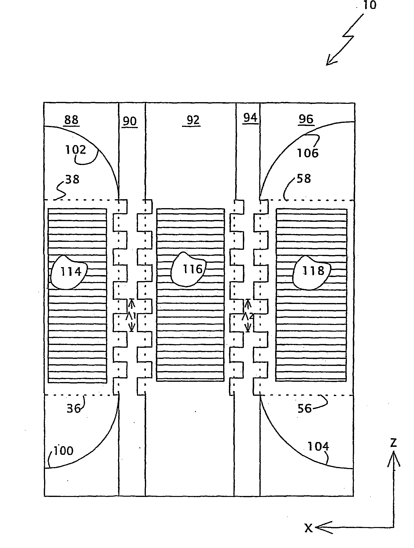
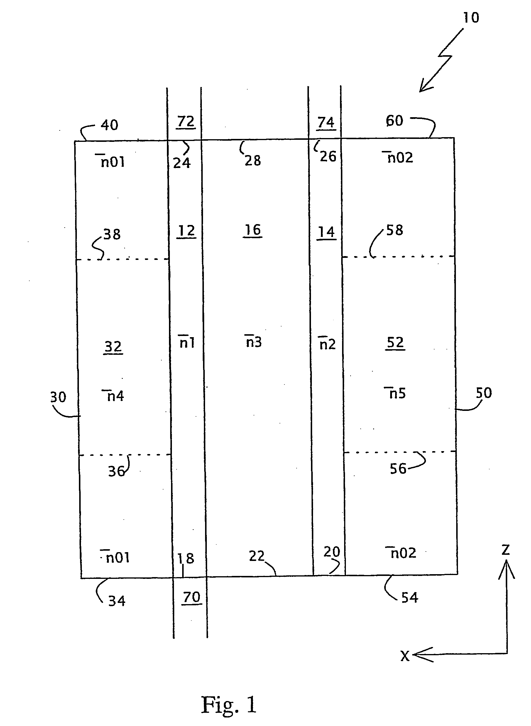
[0041] A first aspect of the present invention is a waveguide structure for implementing the intermediate-state-assisted optical coupler of Vorobeichik et al. A second aspect of the present invention is yet another directional coupler that couples optical modes that propagate separately in taco parallel waveguides via a third optical mode common to the two waveguides. The present invention can be used in optical devices such as power dividers, wavelength filters, optical modulators, attenuators and optical switch matrices.

[0042] The principles and operation of optical couplers according to the present invention may be better understood with reference to the drawings and the accompanying description.

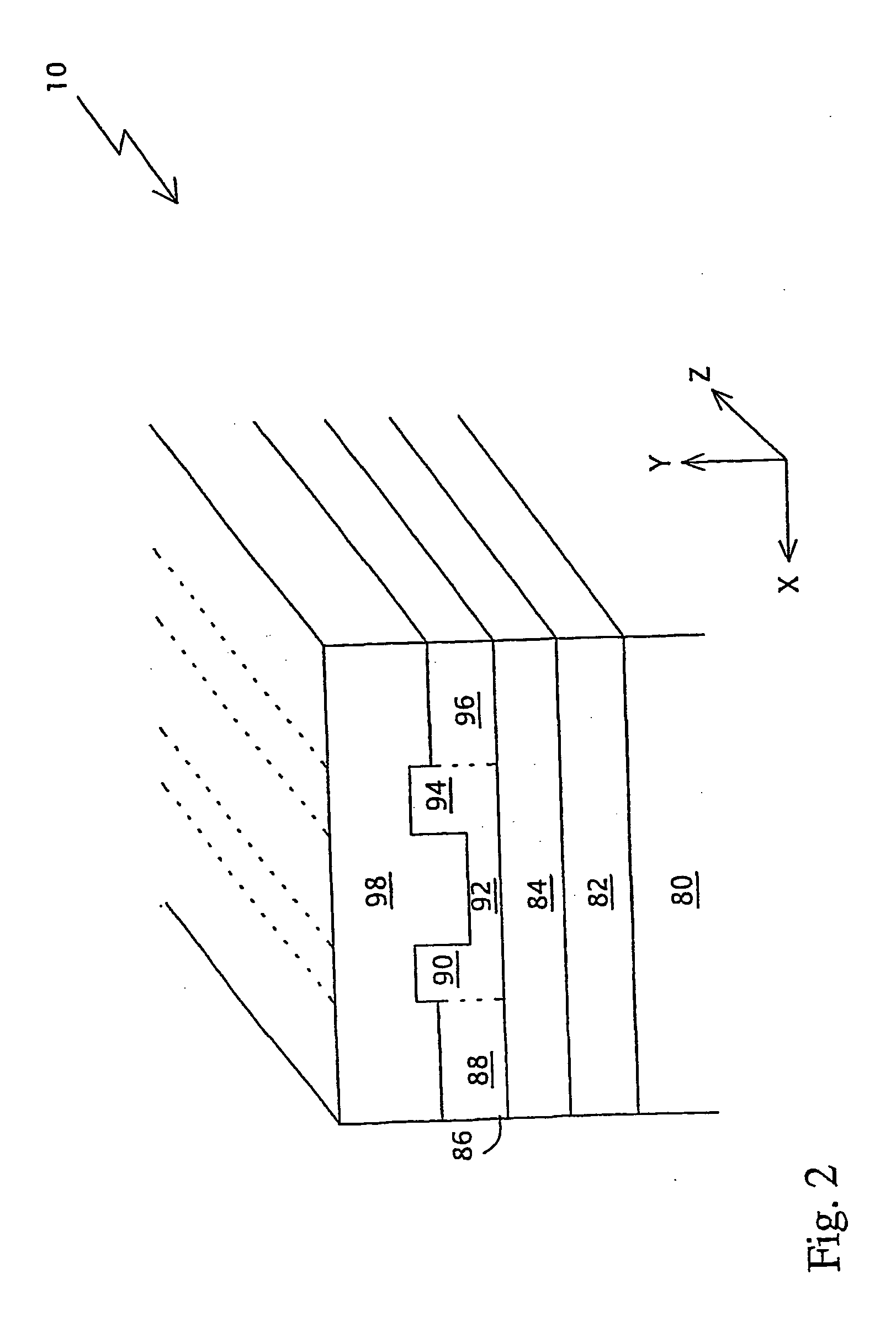
[0043] Referring again to the drawings, FIG. 2 illustrates the physical structure of planar waveguide structure 10. A substrate layer 80 has an index of refraction n.sub.1. A second layer 82 has an index of refraction n.sub.2 which may be smaller than, larger than or equal to n.sub.1. A t...


PUM


Abstract

The invention is a waveguide structure (10) that includes two waveguides (90, 94) flanking a coupling region (92) whose effective refractive index is less than those of the waveguides. Outboard of the waveguides are bounding regions (88, 96) whose effective refractive indices decrease inwards adiabatically at the proximal and distal ends of the bounding regions. The waveguides are coupled optically by periodic perturbations of the waveguide geometry, or by reversible uniform or periodic perturbations of the effective refractive indices. In an optical switch matrix based on the waveguide structure, all the waveguides are straight and parallel. A second aspect of the invention is a directional coupler comprising mechanisms for reversibly and quasiperiodically perturbing the effective refractive indices of the waveguides. The respective envelope functions vary monotonically in opposite senses. Light propagating in one waveguide, in the direction in which that waveguide's envelope function increases, is coupled into the other waveguide.

Description

FIELD AND BACKGROUND OF THE INVENTION[0001] The present invention relates to optical communications devices and, more particularly, to optical couplers.[0002] An optical coupler is a device for exchanging light between two optical waveguides. An optical waveguide is a device for transmitting light over long distances with low losses. It consists of a linearly extended guide portion, having a relatively high index of refraction, encased in a cladding having a lower index of refraction. Light is confined to the guide portion by total internal reflection. Common examples of optical waveguides include planar waveguide structures, which, for the transmission of infrared light, often are made from semiconductors in the same way as integrated circuits, and optical fibers. In an optical fiber, the guide portion conventionally is called a "core".[0003] A directional coupler, in particular, consists of two parallel waveguides in close proximity to each other. The theory of directional coupler...

Claims


Application Information

Patent Timeline
IPC IPC(8): G02B6/12G02B26/08G02B6/122G02F1/01G02F1/313
CPCG02B2006/12107G02B2006/12145G02F1/3133G02F1/3132G02B2006/12147
Inventor VOROBEICHIK, ILYANAREVICIUS, EDVARDASMOISEYEV, NIMRODORENSTEIN, MEIR
Owner OPTUN BVI
Learn More