Communication recovering system for wavelength division multiplexed passive optical network

a technology of wavelength division multiplexing and communication recovery, applied in multiplex communication, fault recovery arrangements, instruments, etc., can solve the problems of reducing reducing the reliability reducing the efficiency of optical subscriber networks, so as to maximize the margin of optical signals, minimize optical loss, and improve economic efficiency and efficiency

Active Publication Date: 2006-05-18
KOREA ADVANCED INST OF SCI & TECH
View PDF3 Cites 87 Cited by
  • Summary
  • Abstract
  • Description
  • Claims
  • Application Information

AI Technical Summary

Benefits of technology

[0016] Therefore, the present invention has been made in view of the above problems, and it is an object of the present invention to provide a wavelength division multiplexed passive optical network (WDM PON) which is capable of minimizing the number of additional elements and optical fibers needed to enhance economical efficiency and efficiency, minimizing optical loss to maximize margin of optical signals, and detecting fault of optical fibers to rapidly recover the optical fibers.

Problems solved by technology

Since the WDM PON has a high transmission speed for optical signals compared with prior art subscriber networks, when communication outage occurs due to cutting or errors of optical fibers or optical components, etc., effects thereof are very serious.
However, since the optical fibers are constructed as outdoor networks, they may be cut at any place and at any time by unexpected causes, such as, road construction, pipe works, and ground collapse, etc.
Especially, when a wavelength division multiplexed optical subscriber network suffers structural breakdown, it is impossible to recover the network, thereby weakening reliability of the optical subscriber network.
Accordingly, since a plurality of multiplexed WDM signals are simultaneously transmitted between the central office and the remote nodes, there may be risk that a plurality of optical signals are lost due to optical fiber fault, which is referred to as communication outage.
Also, since only a few of specific wavelength optical signals are transmitted between the remote nodes and optical network units, there may be risk that the specific wavelength signals are lost due to optical fiber fault.
Although such an optical fiber doubling technology requires an additional optical fiber to form a detouring path, it has still attracted considerable attention since any fault generated in the optical fiber can be rapidly recovered.
However, when the method of FIG. 1b is applied thereto, it has a disadvantage in that performance margin of signals is reduced by more than 3 dB due to optical loss of the star coupler.
Also, it has drawbacks in that fault of optical fiber between the remote nodes and the optical network units cannot be recovered.
On the other hand, although specific methods to implement such an optical fiber doubling technology have been proposed [REFERENCE: A. H. Gnauck, et al., “Reliable architecture for fiber-based broadband local access networks,” US Statutory invention registration, US H2075H, Aug, 5, 2003], when a network is entirely connected using optical fibers, since a plurality of protection fibers and AWGs are required, the networks are extremely complicated.
Also the networks are not cost-effective.
On the other hand, when the number of AWGs is reduced, since usage efficiency for leads of the AWG lead becomes less than 50% and signals are separated using a star coupler, it has disadvantages in that loss of the optical fiber is largely increased.

Method used


Image

  • Communication recovering system for wavelength division multiplexed passive optical network
  • Communication recovering system for wavelength division multiplexed passive optical network
  • Communication recovering system for wavelength division multiplexed passive optical network

Examples


embodiment 1

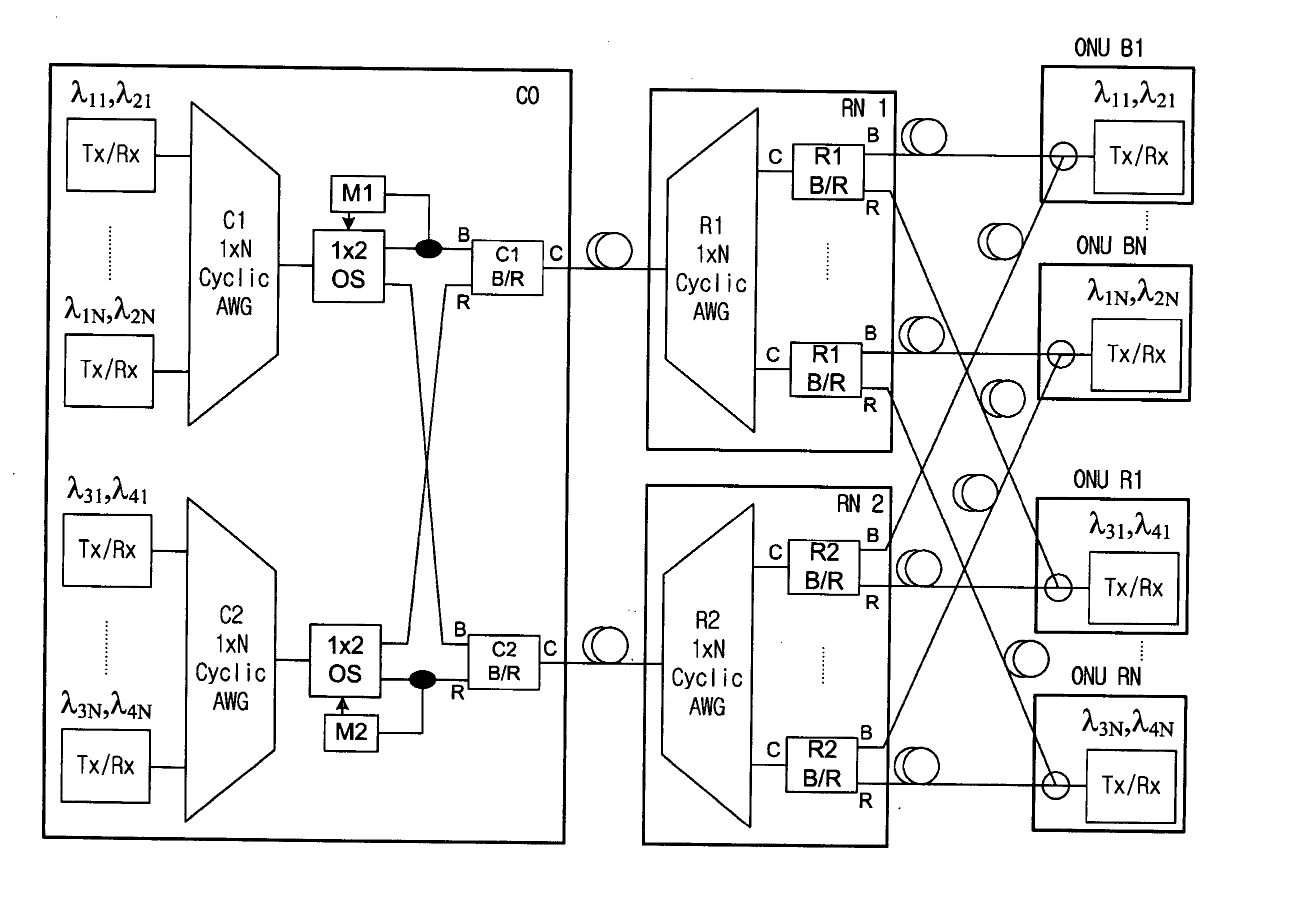
[0061]FIG. 2a is a view describing a communication recovering system in a WDM PON according to a first embodiment of the present invention, and FIG. 2b is a view describing characteristics of blue / red band coupler in a communication recovering system in a WDM PON of FIG. 2a.

[0062] Referring to FIG. 2a, a central office CO in the communication recovering system includes; a first cyclic AWG (hereinafter, cyclic AWG C1) and a second cyclic AWG (herein after cyclic AWG C2) each of which has a 1×N structure and a cyclic pass characteristic; a first 1×2 optical switch (hereinafter, first 1×2 OS) which is installed at multiplexed signal input and output leads of the cyclic AWG C1 and has a 1×2 structure; a second 1×2 optical switch (hereinafter, second 1×2 OS) which is installed at multiplexed signal input and output leads of the cyclic AWG C2; a first blue / red band coupler (hereinafter, B / R band coupler C1) which is connected to each of the 1×2 optical switches; a second blue / red band co...

embodiment 2

[0071]FIG. 2c is a view illustrating a modification of the communication recovering system in a WDM PON according to the first embodiment of the present invention.

[0072] Referring to FIG. 2c associated with FIG. 2a, 1×2 star couplers are installed in the central office CO according to the present invention, instead of the 1×2 optical switches as shown in FIG. 2a, but the optical fiber fault monitors are not installed therein, which is different from FIG. 2a. On the other hand, the ONUs according to the present invention install an 1×2 optical switch, instead of the star couplers as shown in FIG. 2a. Also, the ONUs install optical fibers connecting the 1×2 optical switch to the B / R band coupler R1 or the B / R band coupler, and an optical fiber fault monitor to be connected to the 1×2 optical switch.

[0073] Therefore, when there is a fault in the optical fiber connecting the B / R C1 band coupler to the cyclic AWG R1, or in the optical fiber connecting the B / R band coupler R1 to the 1×2...

embodiment 3

[0075]FIG. 2d is a view illustrating another modification of the communication recovering system in a WDM PON according to the first embodiment of the present invention.

[0076] Referring to FIG. 2d associated with FIG. 2a, the first remote node RN1 includes: a B / R band coupler R11 connected to a B / R band coupler C1; a B / R band coupler R12 connected to a lead of a B / R coupler R11; a first 1×2 star coupler connected to each blue lead of the B / R band couplers R11 and R12; and a cyclic AWG R1 whose multiplexed signal input / output leads are connected to the first 1×2 star coupler. The second remote node RN2 includes: a B / R band coupler R21 connected to a B / R band coupler C2; a B / R band coupler R22 connected to a blue lead of a B / R coupler R21; a second 1×2 star coupler connected to each of red leads of the B / R band couplers R21 and R22; and a cyclic AWG R2 whose multiplexed signal input / output leads are connected to the second 1×2 star coupler. Here, the B / R band coupler R12 and the B / R ...


PUM


Abstract

A communication recovering system for a wavelength division multiplexed passive optical network (WDM PON). The communication recovering system can recover fault of optical fibers between the central office and the remote nodes without additional optical fibers by grouping two remote nodes and employing an AWG having periodic transmission characteristics, and can also simply and rapidly recover such a fault with minimal optical loss using an AWG of 2×N structure and an On-Off optical switch, although protection optical fibers are additionally installed therein. The system can rapidly recover fault of optical fibers between a local office and optical network units, 1:N manner, using 2×2 optical switches, which are installed to each of the optical network units, a reserved transmitter and receiver, and a transceiver. The communication recovering system has advantages in that it can simplify network structure, be cost-effectively implemented, reduce optical loss, and rapidly perform protection of optical fiber fault.

Description

BACKGROUND OF THE INVENTION [0001] 1. Field of the Invention [0002] The present invention relates to a communication recovering system, and more particularly to a communication recovering system for a wavelength division multiplexed passive optical network (WDM PON) which is capable of being implemented with only a single optical fiber using a periodically arrayed waveguide grating (AWG) or protecting / recovering fault of optical fiber by minimizing optical fiber loss, although double optical fibers are used. [0003] 2. Description of the Related Art [0004] Recently, as various data services and multimedia services are rapidly increased through the Internet, a large amount of transmission capacity is needed in a subscriber network. In order to comply with such requirement, a wavelength division multiplexed passive optical network (WDM PON) has attracted considerable attention. Here, the WDM PON is capable of providing a wide variety of services as optical signals whose wavelengths are...

Claims


Application Information

Patent Timeline
Patent Type & Authority Applications(United States)
IPC IPC(8): H04J14/00
CPCH04J14/0226H04J14/0282H04J14/0291H04J14/0295H04J14/0246H04J14/025H04B10/03H04B10/2581
Inventor CHUNG, YUN CHURSON, EUI SEUNGLIM, KYUNG WOOHAN, KWAN HEE
Owner KOREA ADVANCED INST OF SCI & TECH
Why Eureka
Try Eureka