Semiconductor memory
a semiconductor memory and memory technology, applied in the field of semiconductor memory, can solve the problems of obstructing the practical use of the single-intersection memory cell array, increasing array noise during data reading, and reducing the access time and size of the chip including the semiconductor memory, so as to minimize the noise of the array during reading and maximize the margin
- Summary
- Abstract
- Description
- Claims
- Application Information
AI Technical Summary
Benefits of technology
Problems solved by technology
Method used
Image
Examples
first exemplary embodiment
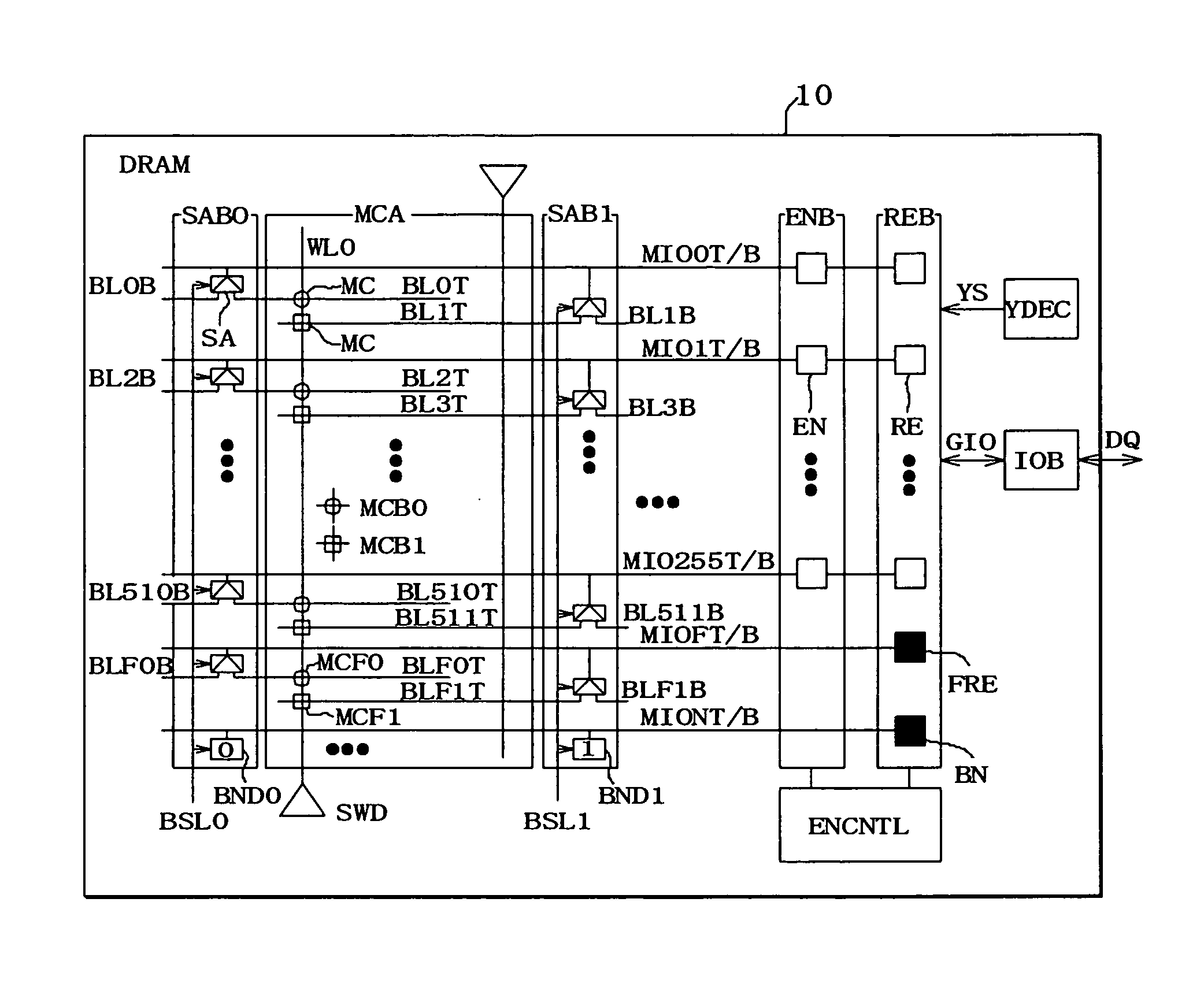
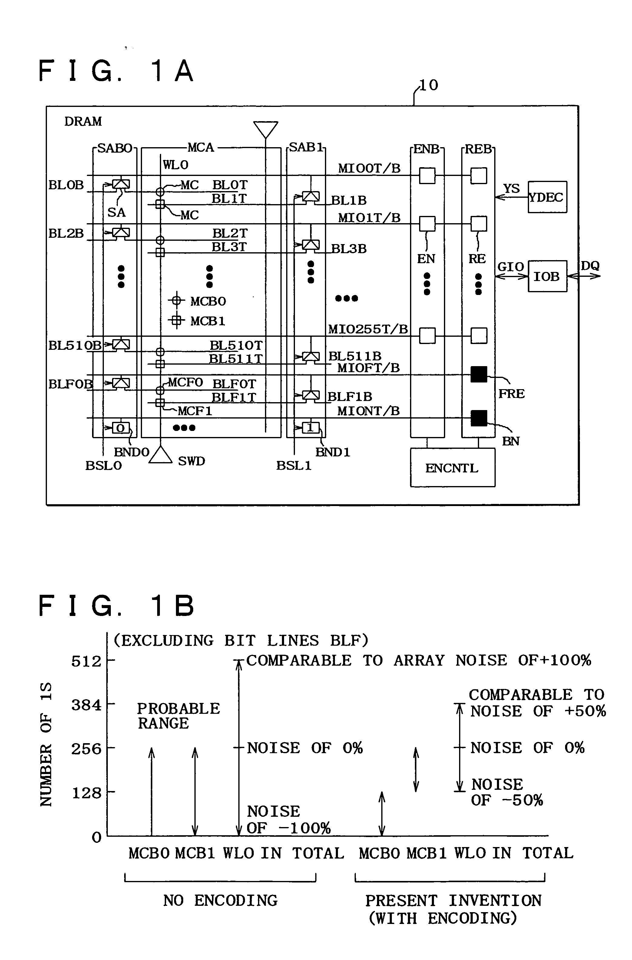
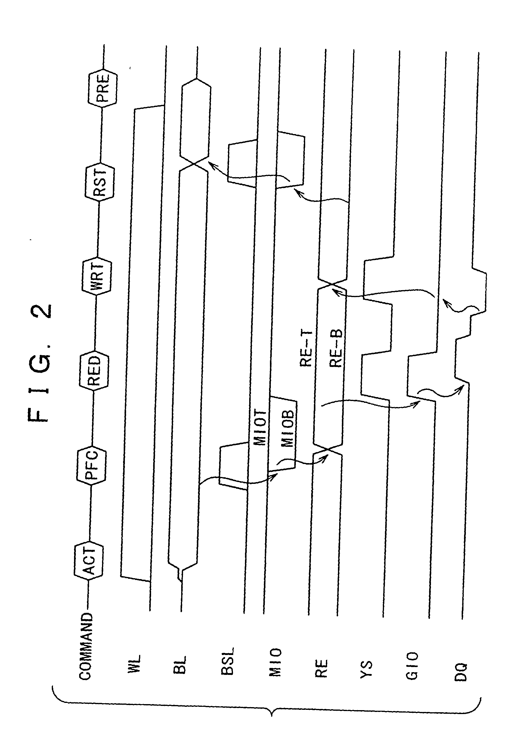
[0034]FIG. 1A shows the circuitry of a low-noise encoding DRAM of a semiconductor memory of a first preferred embodiment of the present invention. FIG. 2 shows the waveforms relevant to the functions performed therein. In the semiconductor chip incorporating the low-noise encoding DRAM 10 of the present invention, an Activate command ACT is issued when data items are to be read or written. The data items stored in memory cells MC constituting a memory cell array MCA are read and held in sense amplifiers SA belonging to sense amplifier banks SAB0 and SAB1.
[0035] After the pre-charging of the sense amplifiers SA is terminated, a sub-word driver SWD activates the word line WL0 so as to read data items from the memory cells MC onto bit lines BL0T, BL1T, etc. The sense amplifiers SA amplify the differences between weak signals developed on the bit lines and reference potentials on side-B bit lines BL0B, BL1B, etc., and hold the results.
[0036] As shown in FIG. 1A, the memory cells inter...
second exemplary embodiment
[0076]FIG. 7 shows an example of the circuitry of another preferred embodiment of the present invention comprising a register-incorporated DRAM. The actions to be performed in the DRAM of this preferred embodiment are described below. An address signal ADD is transmitted to an address buffer ADDBUF. A chip selecting signal / CS, a row address strobe signal / RAS, a column address strobe signal / CAS, and a writing enabling signal / WE are transmitted to a command decoder COMDEC. A clock CLK and a clock-enabling signal CKE are transmitted to a clock generator CLKGEN. The command decoder COMDEC decodes a received control signal and determines an operation mode by selecting any of a reading mode, a writing mode, and a pre-charging mode. A control logic LOGIC produces control signals required depending on the operation mode within a chip. A mode register MDREG holds a current operation mode.
[0077] When an Activate command is received, a row decoder XDEC activates a word line. Data items in a ...
third exemplary embodiment
[0081]FIG. 8 shows another preferred embodiment of the present invention comprising a multi-chip module MCP. A plurality of chips that are hard to be integrated into one chip, such as a DRAM chip 80, a flash memory chip 81, and a logic chip 82 are mounted on a silicon substrate 83, and interconnected using a silicon process. The number of connections is therefore much larger than the one on a normal printed-circuit board, but the area occupied by the mounted chips is reduced.
[0082] Consequently, the number of input / output pins formed on each chip can be increased. The DRAM chip 80 can transmit data items externally via a bidirectional buffer BDB over the main input / output lines MIO shown in FIG. 1. If the logic chip 82 includes the data register bank REB and encoder bank ENB, the DRAM chip 80 can be designed to have standard specifications. The specifications for the logic chip 82 can be modified.
[0083] In this case, the DRAM chip 80 can be mass-produced since it can be adapted to...
PUM
 Abstract
Description
Claims
Application Information
 - R&D
- Intellectual Property
- Life Sciences
- Materials
- Tech Scout
- Unparalleled Data Quality
- Higher Quality Content
- 60% Fewer Hallucinations
Browse by: Latest US Patents, China's latest patents, Technical Efficacy Thesaurus, Application Domain, Technology Topic, Popular Technical Reports.
© 2025 PatSnap. All rights reserved.Legal|Privacy policy|Modern Slavery Act Transparency Statement|Sitemap|About US| Contact US: help@patsnap.com


