Systems and methods for path set-up in a quantum key distribution network

a quantum key and distribution network technology, applied in the field of cryptographic systems, can solve the problems of inability to distribute private keys, all supposedly “secure” networks based on public key technology would become vulnerable, and the logistics of distributing private keys can be prohibitive, so as to reduce the cost and complexity of providing, and ensure the confidentiality of encryption keys. , the effect of ensuring the security of data received at a destination hos

Inactive Publication Date: 2006-06-27
RAYTHEON BBN TECH CORP
View PDF29 Cites 89 Cited by
  • Summary
  • Abstract
  • Description
  • Claims
  • Application Information

AI Technical Summary

Benefits of technology

[0007]Systems and methods consistent with the present invention address this and other needs by implementing a shared, switched network for quantum key distribution. The quantum key distribution (QKD) network of the present invention may include a single “public” network that can be shared across all parties who might desire to exchange keys, therefore, drastically reducing the cost and complexity of providing “any to any” connectivity. The quantum key distribution (QKD) network of the present invention may use quantum cryptographic techniques to assure the confidentiality of encryption keys distributed across a QKD path that may include multiple switches and links in a multi-node QKD network which, thus

Problems solved by technology

Public key cryptographic systems have the drawback that they have never been proven to be difficult to decipher.
All supposedly “secure” networks based on public key technology would thus become vulnerable.
Shared private keys also have the drawback that the logistics of distributing the private keys can be prohibitive.
Although this approach is perfectly feasible for scientific experiments, it does not provide the kind of “anyone to anyone” connectivity that is provided by current communications technology.
Obviously, a large system built along these lines would be impractical, since i

Method used


Image

  • Systems and methods for path set-up in a quantum key distribution network
  • Systems and methods for path set-up in a quantum key distribution network
  • Systems and methods for path set-up in a quantum key distribution network

Examples


Embodiment Construction

[0023]The following detailed description of the invention refers to the accompanying drawings. The same reference numbers in different drawings identify the same or similar elements. Also, the following detailed description does not limit the invention. Instead, the scope of the invention is defined by the appended claims.

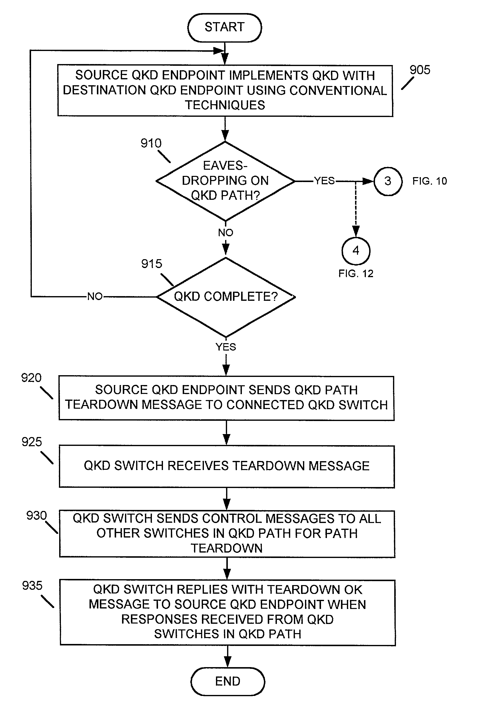
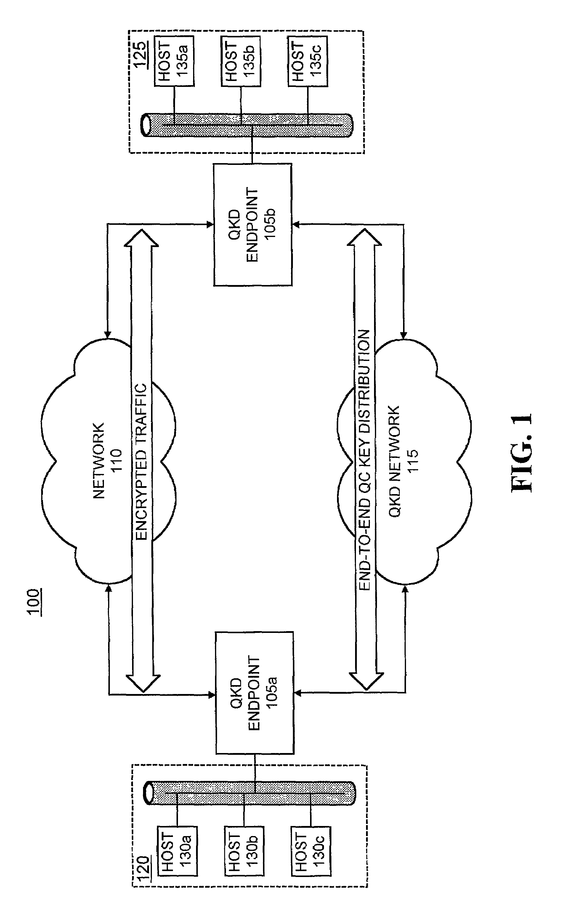
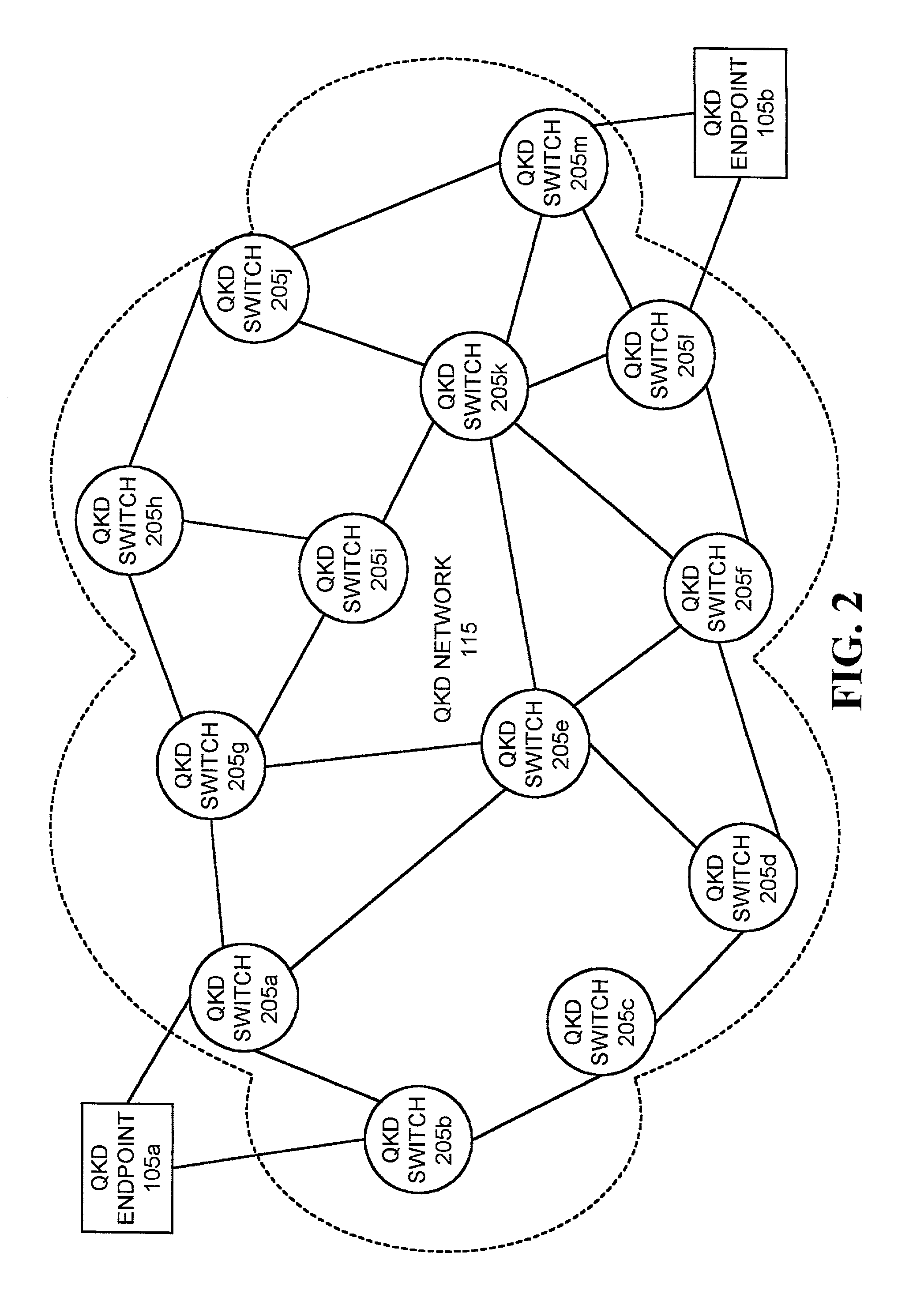
[0024]Systems and methods consistent with the present invention provide mechanisms for distributing encryption keys, using quantum cryptographic techniques, across multiple switches and links in a multi-node quantum key distribution network. Systems and methods consistent with the present invention further provide mechanisms for detecting eavesdropping on the quantum key distribution path and for routing the distribution of encryption keys around the eavesdropping in the network. Systems and methods consistent with the present invention may also discover the location of an eavesdropper at a QKD switch and / or link along the QKD path in the QKD network.

Exemplary Netw...


PUM


Abstract

A system establishes a path for distributing data through an optical network (115). The system includes an optical switch (205a) and a data distribution endpoint (105a). The optical switch (205a) establishes a first encryption key distribution path through the optical network (115), the first encryption key distribution path including multiple optical switches and optical links. The data distribution endpoint (105a) determines whether eavesdropping has occurred on the first encryption key distribution path using quantum cryptography. The optical switch (205a) further establishes a second data distribution path through the optical network (115) responsive to the eavesdropping determination. The second encryption key distribution path includes multiple optical switches and optical links.

Description

RELATED APPLICATION[0001]The present application relates to co-pending application Ser. No. 09 / 944,328, entitled “Quantum Cryptographic Key Distribution Networks with Untrusted Switches,” filed on even date herewith and having assignee in common with that of the instant patent application. The disclosure of the co-pending application is incorporated by reference herein.FIELD OF THE INVENTION[0002]The present invention relates generally to cryptographic systems and, more particularly, to systems and methods for distributing encryption keys in quantum cryptographic networks.BACKGROUND OF THE INVENTION[0003]Conventional packet-switching networks permit cheap and reliable communications independent of the distance between a source node and a destination node in the network. These conventional networks often rely upon either public keys or shared private keys to provide privacy for messages that pass through the network's links. Public key cryptographic systems have the drawback that the...

Claims


Application Information

Patent Timeline
IPC IPC(8): H04L9/00
CPCH04L9/0827H04L9/0852
Inventor ELLIOTT, BRIG BARNUM
Owner RAYTHEON BBN TECH CORP
Why Eureka
Try Eureka