Fill and compaction roller using replaceable cleat assemblies with extended service life

a technology of replaceable cleats and rollers, which is applied in the direction of construction, foundation engineering, roads, etc., can solve the problems of reducing the service life of wear caps and cleat assemblies, and long service life, and achieve the effect of inhibiting the twisting of the cap uni

Inactive Publication Date: 2004-02-19
CARON COMPACTOR
View PDF10 Cites 21 Cited by
  • Summary
  • Abstract
  • Description
  • Claims
  • Application Information

AI Technical Summary

Benefits of technology

[0007] It is another object of the present invention to provide an improved cleat assembly in which the wear cap can be readily replaced so as to avoid the wearing away the mounting base carrying such wear cap.
[0009] It is a further object of the invention to provide an improved cleat assembly for fill and compaction roller characterized by means restraining twisting between the wear cap and base.
[0011] An additional object of the invention is to provide a cleat assembly having a readily removable cap unit serving to engage upon a base in secure mortise and tenon joints thereby inhibiting twisting of the cap unit with respect to the base.

Problems solved by technology

It has been observed that due in large degree to manufacturing tolerances that the use of removable wear caps coupled to a fixed base, in severe service exposes the assembly to twisting forces which in time materially reduce the service life of the wear cap and cleat assembly.
Moreover, landfill operators expect very long service life of the compaction rollers and cleat assemblies, some required assurances that these components will render a service life on the order of 20,000 hours.

Method used


Image

  • Fill and compaction roller using replaceable cleat assemblies with extended service life
  • Fill and compaction roller using replaceable cleat assemblies with extended service life
  • Fill and compaction roller using replaceable cleat assemblies with extended service life

Examples


Embodiment Construction

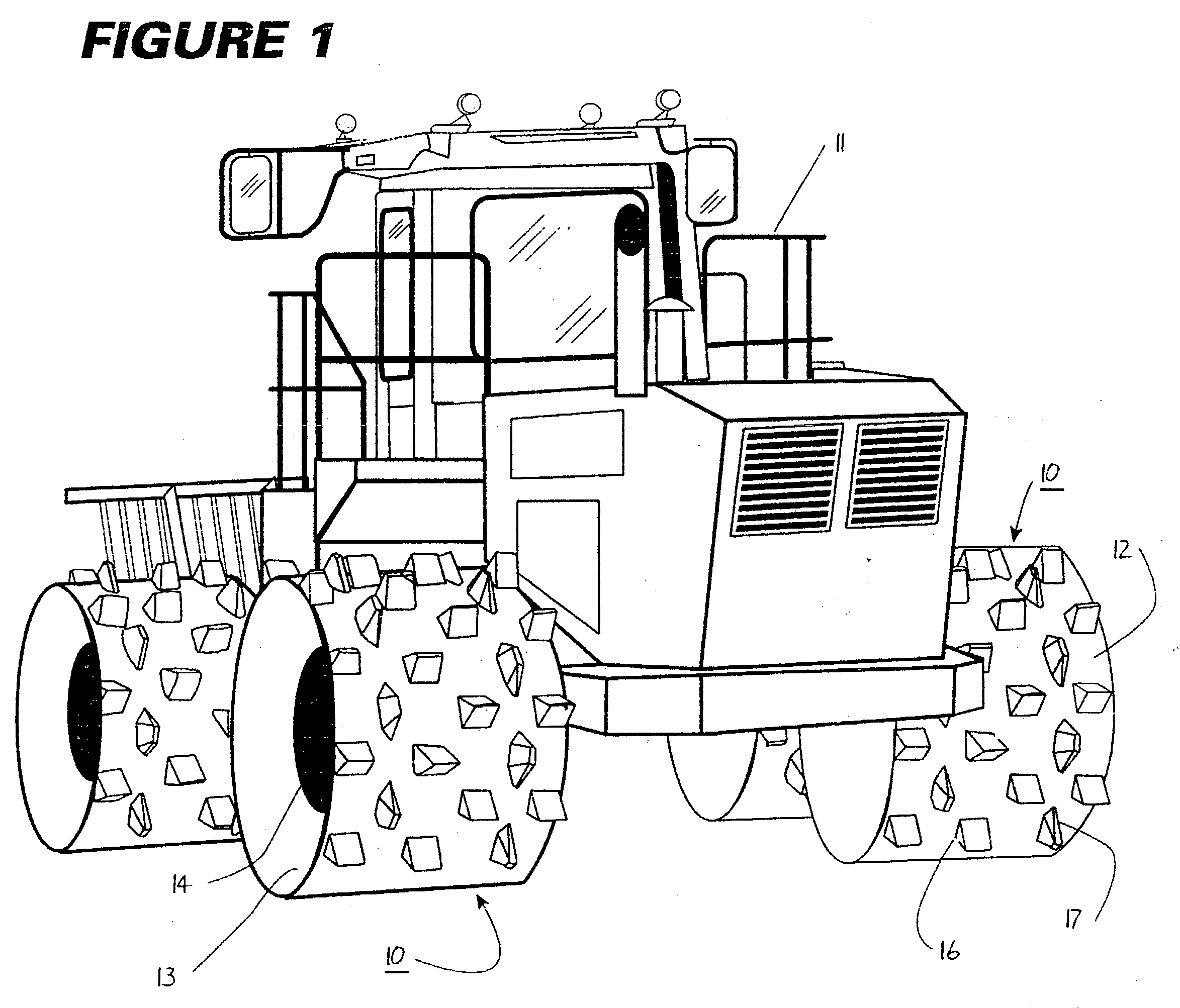
[0035] A compaction roller 10 constructed according to the present invention is illustrated in FIG. 1 mounted upon a power-driven trash compaction vehicle 11 of high gross vehicular weight, the roller 10 normally being deployed in sets of four as shown. The compaction roller 10 includes a rigid cylindrical body or rim 12 connected to a centrally disposed conical web 13 which in turn is rigidly secured to central wheels structure 14 shown diagrammatically but may be constructed according to U.S. Pat. No. 3,724,342 assigned to Caron Compactor Company to incorporate cushioning elements and the like.

[0036] The wheel or roller 10 is shown mounted upon a very heavy duty compactor. vehicle, one in the gross vehicle weight range of 70,000-120,000 lbs. The high vehicular weights are desirable to achieve high compaction densities in the sanitary land fill thereby to increase the capacity life of the landfill.

[0037] The cylindrical rim 12 of each of the four wheels shown in FIG. 1 is equipped ...


PUM


Abstract

A compaction roller for mounting on a driven compaction vehicle is equipped with both destructive and tractive, highly wear resistant cleat assemblies. The later includes readily removable wear caps with bulbous full height corner portions and broad wear faces. Anti twist projections and complementary recesses including mortise and tenon type locks at the interface of the wear cap and support bases reduce relative movements between the parts under sever working forces.

Description

[0001] This application is a continuation-in-part of application Serial No. 09 / 846,082, filed Apr. 30, 2001, which is a continuation-in-part of application Serial No. 09 / 565,824, filed May 5, 2000, abandoned.[0002] This invention generally concerns compaction machinery such as a roller or wheel for mounting upon a driven compactor vehicle or tractor, the roller having both destructive and tractive characteristics adapted to break up, crush, grind and compact throwaway materials commonly delivered to a sanitary land fill operations. More particularly this invention is characterized by cleat assemblies including removable wear caps configured for a long service life.[0003] Compaction rollers and wheels used on landfill operations and particularly sanitary landfill operations are equipped generally with cleats or feet of the type for grinding and crushing materials to reduce the size and bulk of the material. As shown in the assignee's prior patents, U.S. Pat. No. 3,922,106 and 4,919,5...

Claims


Application Information

Patent Timeline
Patent Type & Authority Applications(United States)
IPC IPC(8): E02D3/026
CPCE02D3/026
Inventor CARON, JAMES O.CARON, SCOTT F.P.
Owner CARON COMPACTOR
Why Eureka
Try Eureka