:
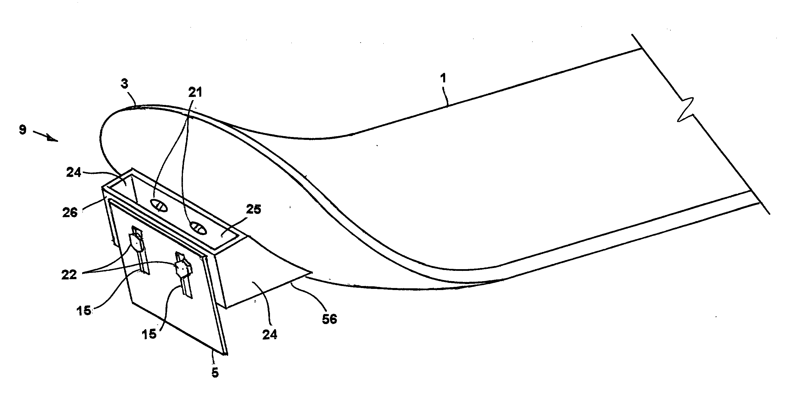
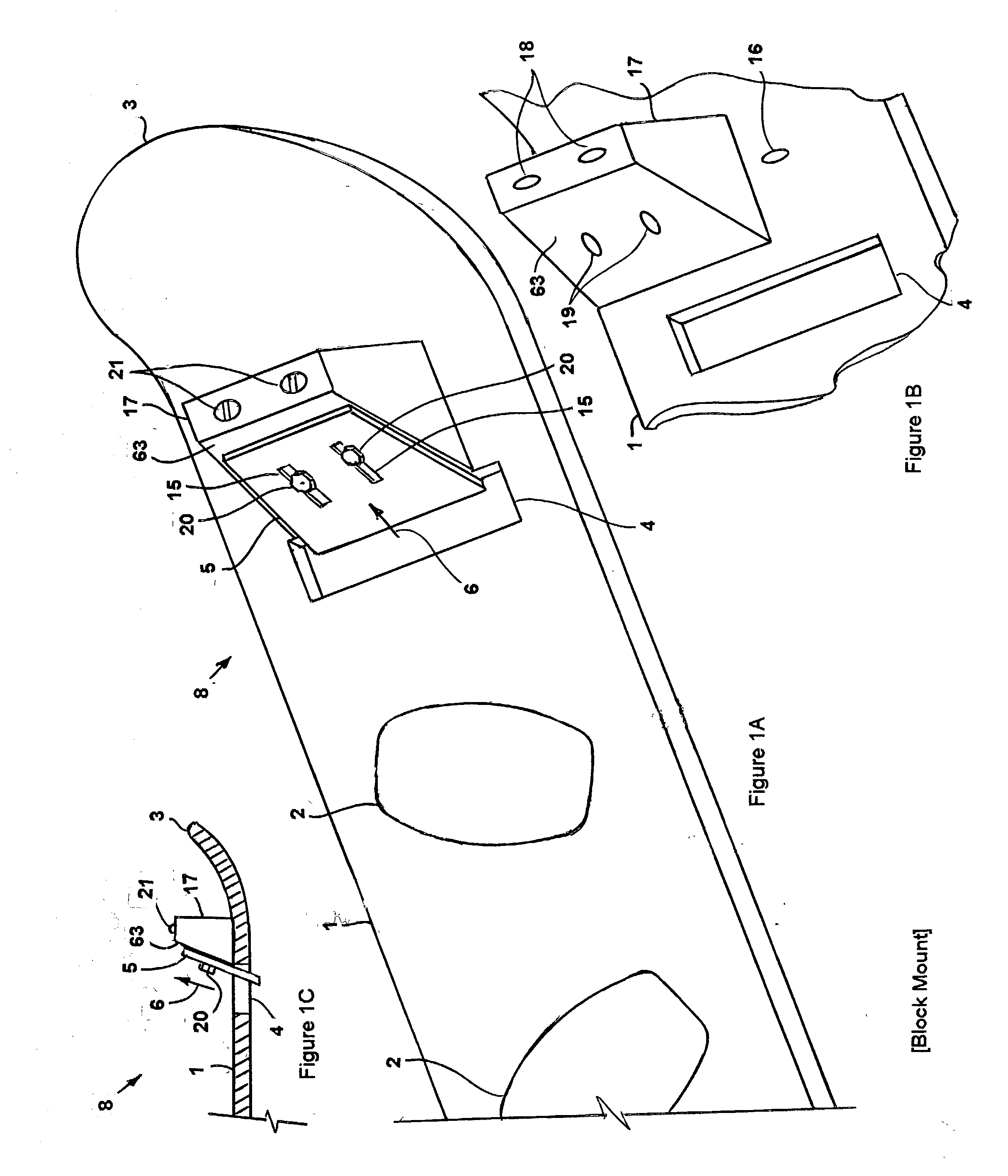
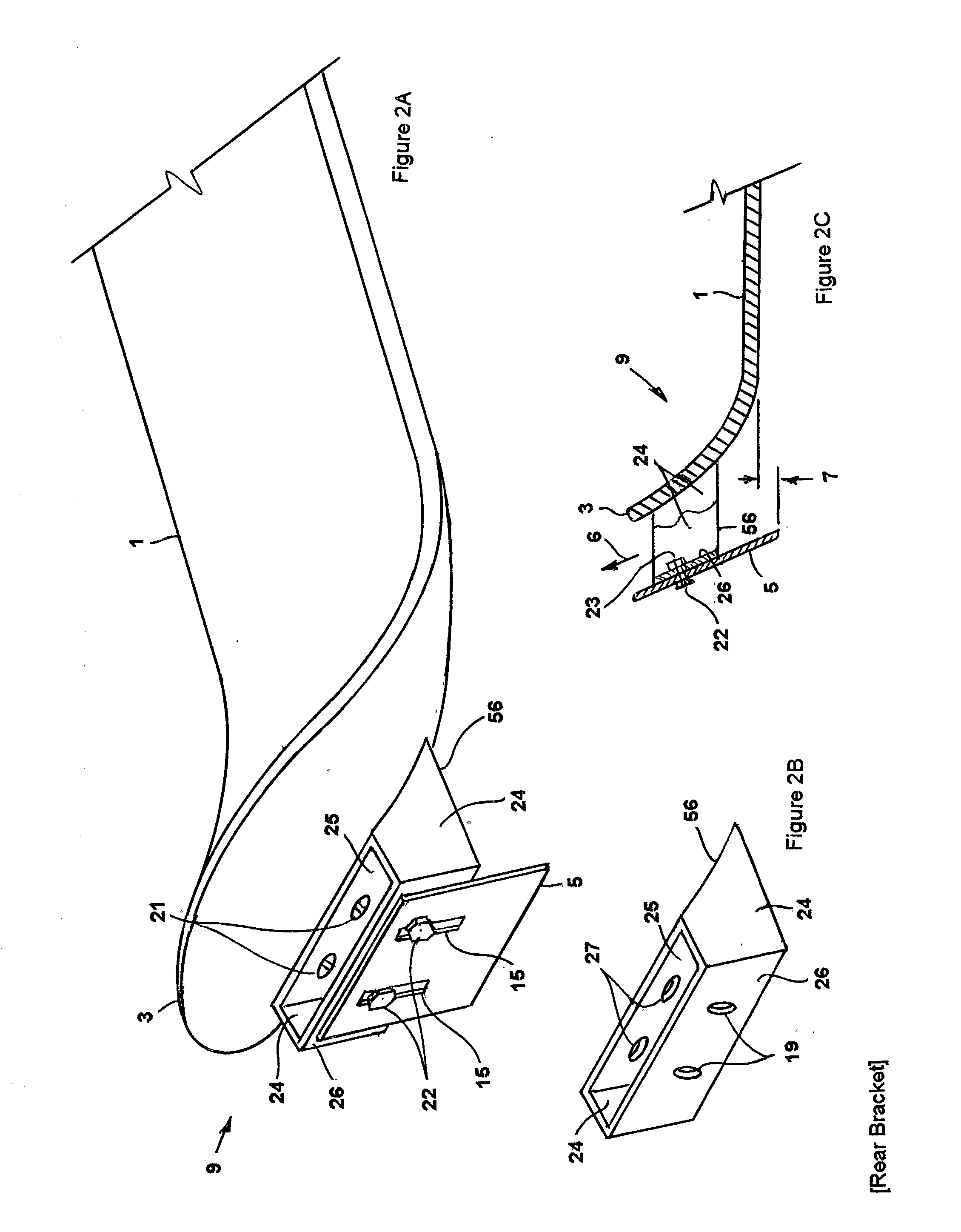
[0052] FIG. 1A presents a perspective view of a snow board, indicated by the general reference number 1, schematic representation of the outline of a pair of boot clamps 2 affixed to the upper surface of said snow board 1 along the center line of said snow board 1, said boot clamps 2 oriented to one side of said snow board 1 and oriented slightly apart from each other. The braking devices 8, 9, 10, 11, 12, 13, 14, 48, 51 are positioned rearward of the noted bindings 2. In the preferred embodiment of the present invention, the braking member is a blade 5 which, when fully extended downward, is oriented straight down or is inclined downward and forward, said blade 5 extends downward by about 1/2 inch or less and extends about 4 inches across the middle of the rear bottom surface or across the middle of the end of said snow board 1.
[0053] Nine embodiments of the present invention are specified as follows:
[0054] Flange Brake (FIGS. 9A, 9B, 9C)
[0055] A device termed a flange brake for slowing a training snow board 1, designated by the general reference number 48, comprised of a vertically oriented blade 5 affixed at its upper edge to the rear edge of a flat horizontal base piece 50, said blade 5 having a lower edge parallel to the bottom of said snow board 1 and said blade 5 perpendicular to the length of said snow board 1 and centered on the center line of said snow board 1 and under the rear half of the snow board 1, said base piece 50 having at least one hole 27 therein and affixed to the bottom of said snow board 1, by affixing means, said affixing means comprised of at least one mounting screw 21 centrally located on the face of said base piece 50 and securing said base piece 50 through said at least one hole 27 to said snow board 1. The preferred embodiment of the present invention has two mounting holes 27 and two mounting screws 21 passing through said mounting holes 27 securing said base piece 50 to the bottom of the snow board 1 as shown in FIGS. 9A and 9B. Said flange brake 48 can be installed in pairs as shown in FIG. 9C on the rear bottom surface of said snow board 1 on each side, said blades 5 projecting below and to each side of said snow board 1.
[0056] The functioning of this embodiment of the present invention is as follows. When said snow board 1 is being ridden by a user, said blade 5 engages and cuts the snow beneath the snow board 1 reducing the speed of the snow board 1 by providing a fixed amount of drag. The amount of drag realized can be varied by replacement of the flange brake 48 with one having a deeper or shallower blade 5 to provide a different depth of cut and thus a different amount of drag.
[0057] The following eight embodiments 8, 9, 10, 11, 12, 13, 14, 51 of the present invention provide a slot 4 in said snow board 1, as shown in FIGS. 1A, 1B, 1C, 3A, 4A, 5A, 8A and 8B, or an opening ahead of said blade 5, in the supporting structure for the blade, when the braking device is attached to the rear end 3 of said snow board 1, as shown in FIGS. 2A, 2C, 6A and 7 The cut snow passes upward through this slot 4 or opening in the supporting structure as shown by motion arrow 6. It is understood that for these embodiments, these are the preferred arrangements but that such a slot 4 or opening is not essential for them to function properly. The object is to provide a fixed amount of drag for the snow board 1 when in use providing a fixed depth of cut 7, as shown in FIG. 2C. By cutting the contacted snow and reducing the speed of the snow board 1, the level of skill of an individual user is accommodated. It is this constancy of drag and the resulting reduction in the speed of the snow board which directly contributes to the development of the user's skill. It also tends to build confidence in the user. In the following eight embodiment of the present invention, the preferred dimensions of the slot or opening ahead of the cutting blade is about 4 inches by 1 inch.
[0058] Rear Bracket (FIGS. 2A, 2B, 2C)
[0059] A device termed a rear bracket for slowing a training snow board 1, designated by the general reference number 9, comprised of a bracket 56 affixed to the upcurved portion of the rear end 3 of said snow board 1 by mounting means, said bracket 56 comprised of a curved base piece 25 conformed to the shape of the bottom of said rear end 3, two sides 24, each affixed vertically to the outer edges of said base piece 25, a rear plate 26 affixed on each outer edge to the rear edge of each of said side pieces 24 and having at least one adjusting hole 19 centrally located therein, at least one mounting hole 27 in said base piece 25 as shown in FIG. 2B, said mounting means comprised of at least one mounting screw 21 passing through said at least one mounting hole 27 and securing said base piece 25 of said bracket 56 to the bottom rear side of said snow board 1 as shown in FIGS. 2A and 2C, a blade 5 comprised of a rectangular plate and at least one vertical slot 15 centrally located therein and a bottom edge parallel to the bottom center portion of said snow board 1, said blade 5 slidably affixed to the rear of said rear plate 26 by at least one bolt 22 passing through said at least one slot 15 in said blade 5 and through at least one adjusting hole 19 in said rear piece 26 and adjustably secured by a nut 23 as shown in FIGS. 2A and 2C, said bracket 56 formed as an open ended box-like vertically oriented structure, rectangular in cross section, whereby snow cut by said blade 5 passes upward through said open ended box-like structure as shown by direction arrow 6.
[0060] The functioning of the preferred embodiment of the present invention is realized by adjustable affixing means comprised of two slots 15, two matching holes 19, two bolts 22 and two nuts 23, whereby said blade 5 is adjustably affixed, by said adjustable affixing means, to locate the bottom edge of said blade 5 at or below the bottom plane of the central portion of said snow board 1 as shown in FIGS. 2A and 2C.
[0061] Grooved Rear Brake (FIGS. 6A, 6B)
[0062] A device termed a grooved rear brake for slowing a training snow board 1, designated by the general reference number 13, comprised of a bracket 56 affixed to the bottom of said upcurved portion of the rear end 3 of said snow board 1 by mounting means, said bracket 56 comprised of a curved base plate 45 conformed to the shape of the bottom of said rear end 3, at least one mounting hole 27 centrally located in said curved base plate 45, two side plates 44, each affixed vertically to the outer edges of said base plate 45 and each having an outwardly directed flange 60 as shown in FIGS. 6A and 6B forming the rear portion of a groove 41, a channel 43, said channel comprised of a base 62 and having forwardly facing vertical flanges 61, said flanges 61 affixed, on each side at their forward edges to the rear edges of said outwardly directed flanges 60, a threaded hole 33 centrally located in said channel base 62, said mounting means comprised of at least one mounting screw 21 passing through said at least one mounting hole 27 and securing said base plate 45 of said bracket 56 to the bottom rear end 3 of said snow board 1 as shown in FIG. 6A, a blade 5 adjustably affixed by sliding attachment means to said bracket 56, said blade 5 having a vertical recessed groove 42 centrally located on the rear of said blade 5 and a bottom edge parallel to the bottom of said snow board 1, said blade 5 slidably affixed within said groove 41 by said sliding attachment means by a thumb screw 40 threaded through said threaded hole 33 and by rotation and pressing against said blade 5 within said recessed groove 42, adjustably securing said blade 5 within said grooves 41 against said outwardly directed flanges 61, the interior of said bracket 56 and said blade 5 formed as an open ended box-like vertically oriented structure, rectangular in cross section, whereby snow cut by said blade 5 passes upward through said box-like structure as indicated by direction arrow 6, and whereby the vertical length of said recessed grove 42 is at least as long as the range of motion of the blade 5, the motion of said blade 5 restrained by the tip of said thumb screw 40 in said recessed grove 42 whereby when the bottom edge of said blade 5 is at or above the plane of said snow board 1, said tip of said thumb screw 40 is at the bottom of said recessed groove 42 and when the bottom edge of said blade 5 is fully lowered, said tip of said thumb screw 40 is at the top of said recessed groove 42.
[0063] The functioning of this embodiment of the present invention is by adjusting the position of said blade 5 by sliding said blade 5 to locate the bottom edge of said blade 5 at or below the bottom plane of the central portion of said snow board 1 and by securing said blade 5 with said thumb screw 40 thereby cutting snow and slowing said snow board 1.
[0064] Rear Pivot Brake (FIG. 7)
[0065] A device termed a rear pivot brake for slowing a training snow board 1, designated by the general reference number 14, comprised of a bracket 56 affixed to the upcurved portion of the rear end 3 of said snow board 1 by mounting means, said bracket 56 comprised of a curved base 30 conformed to the shape of said rear end 3, at least one mounting hole 27 centrally located in said curved base 30, said mounting means comprised of at least one mounting screw 21 passing through said at least one mounting hole 27 and securing said curved base 30 of said bracket 56 to the bottom rear side of said snow board 1 as shown in FIG. 7, two sides 31 each affixed vertically to the outer edges of said curved base 30, a pivot hole 35 in each of said sides 31 proximate to said curved base 30, a curved slot 32 in each of said sides 31 distal from said curved base 30 and the arcs of said curved slots concentric to said pivot holes 35, a rectangular blade 5 and two vertical flat sides 29 affixed to the outer ends of said blade 5 and extended forward toward, interior to and proximate to said sides 31 and a pivot hole 34 in each of said sides 29 at the distal ends of said sides 29 away from said blade 5, a adjustment hole 19 in each of said sides 29 proximate to said blade 5, centered on said holes 35 and spaced from said pivot hole 34 a length equal to the distance between said pivot hole 34 and said curved slot 32, two bolts 36 rotably securing said sides 29, 31 one on each side of said bracket 56 said pivot hole 35 of said side 31 to said pivot hole 34 of said side 29, said bolt 36 passing through said holes 34, 35 and secured by a lock nut 39 as shown in FIG. 7, two bolts 46 passing through said hole 19 one on each interior side 29 and through said curved slot 32 in said side 31 and passing through a washer 38 and secured by a wing nut 47, whereby said blade 5 is rotably pivoted about said pivot holes 34, 35 and is adjustably fixed by said wing nuts 47 by pressure on said sides 29, 31 whereby when said blade 5 is below the plane of the bottom of said snow board 1 said bolt 46 is proximate to or at the upper extent of said curved slots 32 and when said blade 5 is at or above the plane of the bottom of said snow board 1 said bolt 46 is proximate to or at the lower extent of said curved slots 32.
[0066] The functioning of the preferred embodiment of the present invention is by adjusting the position of said blade 5 by rotating the blade 5 locating the bottom edge of said blade 5 at or below the bottom plane of the central portion of said snow board 1 by securing said adjusting bolts 46 with said wing nuts 47, whereby when said blade 5 is below the plane of the bottom of the snow board 1, snow is cut and carried upward through said bracket 56 as shown by direction arrow 6 thereby creating drag and slowing said snow board as shown in FIG. 7. It is understood that the sides 29 of the blade can be configured to be exterior to the sides 31 of the bracket 56 or that the respective locations of said slots 32 and said adjusting holes 19 on their respective sides 29, 31 can be reversed while using the same adjustment means.
[0067] Block Mount (FIGS. 1A, 1B, 1C)
[0068] A device termed a block mount for slowing a training snow board 1, designated by the general reference number 8, said snow board 1 modified by having a vertical slot 4 through said snow board 1 on the center line of said snow board 1 and between the rear of two boot clamps 2 and the rear of said snow board 1, the length of said slot 4 perpendicular to the center line of said snow board 1, said block mount 8 comprised of a block 17 affixed to the top rear surface of said snow board 1 by mounting means, said block 17 comprised of a front sloped surface 63, at least one adjusting hole 19 located centrally in the face of said sloped surface, said mounting means comprised of at least one mounting hole 18 passing vertically downward from the top of said block 17 downward through its bottom and at least one mounting screw 21 passing downward through said at least one mounting hole 18 and into at least one mounting hole 16 in the upper surface of said snow board 1, said block 17 adjacent to and at the rear of said slot 4, a blade 5 comprised of a rectangular plate and at least one vertical slot 15 centrally located therein and a bottom edge parallel to the bottom center portion of said snow board 1, said blade 5 slidably affixed to said block 17 by at least one adjusting screw 20 passing through said at least one slot 15 in said blade 5 and through at least one adjusting hole 19 in said block 17 as shown in FIGS. 1A, 1B and 1C, whereby snow cut by said blade 5 passes upward through said slot 4 as shown by direction arrow 6.
[0069] The functioning of the preferred embodiment of the present invention is realized by adjustable affixing means comprised of two slots 15 in said blade 5, two matching holes 19, two adjusting screw 20, whereby said blade 5 is adjustably affixed to said block 17, by said adjustable affixing means, to locate the bottom edge of said blade 5 below the bottom plane of said snow board 1 as shown in FIGS. 1A, 1B and 1C, thereby cutting snow and slowing said snow board 1.
[0070] Grooved Blade Mount (FIGS. 4A, 4B)
[0071] A device termed a grooved blade mount for slowing a training snow board 1, designated by the general reference number 11, said snow board 1 modified by having a vertical slot 4 through said snow board 1 on the center line of said snow board 1 and between the rear of two boot clamps 2 and the rear end 3 of said snow board 1, the length of said slot 4 perpendicular to the center line of said snow board 1, said grooved blade mount 11 comprised of a bent support designated by the general reference number 59 affixed to the top rear surface of said snow board 1 by mounting means adjacent to and at the rear of said slot 4, said bent support 59 comprised of a sloping plate 58 and a threaded adjusting hole 33 located centrally in the face of said sloping plate 58, a horizontal base plate 57 fixed along its forward edge to the bottom edge of said sloping plate 58, at least one mounting hole 27 centrally located in said base plate 57, at least one mounting screw 21 passing downward through said at least one mounting hole 27 into the upper surface of said snow board 1 whereby the forward edge of said sloping plate 58 is at and adjacent to the rear of said slot 4, a blade 5 comprised of a rectangular plate and on each upper side a channel 43 affixed to said plate, said channels 43 parallel to each other and facing each other across the rear side of said blade 5 forming grooves 41 on either side of said blade 5, a vertical recessed groove 42 centrally located on the rear side of said blade 5 and the bottom edge of said blade 5 parallel to the bottom of said snow board 1, said blade 5 adjustably affixed by sliding attachment means downward over said sloping plate 58 of said bent support 59 by sliding said channels 43 downward over the top of said sloping plate 58 and securing said blade 5 with a thumb screw 40, said thumb screw 40 passing through said threaded hole 33 and adjustably securing said blade 5 with the tip of said thumb screw 40 resting against said recessed groove 42, and by rotation and pressing against said blade 5 within said recessed groove 42, adjustably securing said blade 5 within said grooves 41 on the sides of said blade 5, whereby snow cut by said blade 5 passes upward through said slot 4, whereby the vertical length of said recessed groove 42 is at least as long as the range of motion of said blade 5, the motion of said blade 5 restrained by the tip of said thumb screw 40 in said recessed groove 42 whereby when the bottom edge of said blade 5 is at or above the plane of said snow board 1, said tip of said thumb screw 40 is at the bottom of said recessed groove 42 and when the bottom edge of said blade 5 is fully lowered, said tip of said thumb screw 40 is at the top of said recessed groove 42.
[0072] The functioning of the preferred embodiment of the present invention is by adjusting the position of said blade 5 by sliding said blade 5 locating the bottom edge of said blade 5 below the bottom plane of the bottom of said snow board 1 and by securing the blade 5 with said thumb screw 40 as shown in FIGS. 4A and 4B, thereby cutting snow and slowing said snow board 1.
[0073] Grooved Center Mount (FIGS. 5A, 5B)
[0074] A device termed a grooved center mount for slowing a training snow board 1, designated by the general reference number 12, said snow board 1 modified by having a vertical slot 4 through said snow board 1 on the center line of said snow board 1 and between the rear of two boot clamps 2 and the rear end 3 of said snow board 1, the length of said slot 4 perpendicular to the center line of said snow board 1, said grooved blade mount 11 comprised of a bent support designated by the general reference number 59 affixed to the top rear surface of said snow board 1 by mounting means adjacent to and at the rear of said slot 4, said bent support 59 comprised of a sloping plate 58 and a threaded adjusting hole 33 located centrally in the face of said sloping plate 58 and on each upper side a channel 43 affixed to said sloping plate 58, said channels 43 parallel to each other and facing each other across the forward side of said sloping plate 58 forming grooves 41, a horizontal base plate 57 affixed along its forward edge to the bottom edge of said sloping plate 58, said mounting means comprised of at least one mounting hole 27 centrally located in said base plate 57, at least one mounting screw 21 passing downward through said at least one mounting hole 27 into the upper surface of said snow board 1 whereby the forward edge of said sloping plate 58 is at and adjacent to the rear of said slot 4, a blade 5 comprised of a rectangular plate, a vertical recessed groove 42 centrally located on the rear side of said blade 5 and the bottom edge of said blade 5 parallel to the bottom of said snow board 1, said blade 5 adjustably affixed by sliding said blade 5 into said channels 43 on the top of said sloping portion 58 of said bent support 59 and securing said blade 5 with a thumb screw 40, said thumb screw 40 passing through said threaded hole 33 and adjustably securing said blade 5 with the tip of said thumb screw 40 resting against said recessed groove 42, and by rotation and pressing against said blade 5 within said recessed groove 42, adjustably securing said blade 5 within said grooves 41 on the sides of said sloping plate 58, whereby snow cut by said blade 5 passes upward through said slot 4 as shown by direction arrow 6 and whereby the vertical length of said recessed groove 42 is at least as long as the range of motion of the blade 5, the motion of said blade 5 by the tip of said thumb screw 40 in said recessed groove 42 whereby when the bottom edge of said blade 5 is at or above the plane of said snow board 1, said tip of said thumb screw 40 is at the bottom of said recessed groove 42 and when the bottom edge of said blade 5 is fully lowered, said tip of said thumb screw 40 is at the top of said recessed groove 42, as shown in FIGS. 5A and 6A.
[0075] The functioning of the preferred embodiment of the present invention is by adjusting the position of said blade 5 by sliding the blade to locate the bottom edge of said blade 5 at or below the bottom plane of the bottom of said snow board 1 and by securing the blade 5 with said thumb screw 40, as shown in FIGS. 5A and 5B, thereby cutting snow and slowing said snow board 1.
[0076] Pivot Brake (FIGS. 3A, 3B)
[0077] A device termed a pivot brake for slowing a training snow board 1 designated by the general reference number 10, said snow board 1 modified by having a vertical slot 4 through said snow board 1 on the center line of said snow board 1 and between the rear of two boot clamps 2 and the rear of said snow board 1, said pivot brake 10 comprised of a bracket 56 affixed to the upper surface of the rear end 3 of said snow board 1 by mounting means, said bracket 56 comprised of a horizontal flat base 30, at least one mounting hole 27 centrally located therein, said mounting means comprised of at least one mounting screw 21 passing through said at least one mounting hole 27 and securing said base 30 of said bracket 56 to the bottom rear side of said snow board 1 as shown in FIG. 3B, two sides 31 each affixed vertically to the outer edges of said base 30, a pivot hole 35 in each of said sides 31 in the rear portion of said sides 31 and proximate to said base 30, a curved slot 32 in each of said sides 31 forward of said pivot holes 35 and the arcs of said curved slots concentric to said pivot holes 35, a rectangular blade 5, a rectangular top plate 28 affixed at its forward edge to the top edge of said blade 5, extending rearward, two vertical flat sides 29, the forward edges of said flat sides 29 affixed to the outer upper ends of said blade 5 and the upper dges of said flat sides 29 affixed to the outer edges of said top plate 28, said flat sides 29 extended downward, interior to and proximate to said sides 31 and a pivot hole 34 in each of said sides 29 at the distal ends of said sides 29 away from said blade 5, a threaded adjustment hole 33 in each of said sides 29 proximate to said blade 5 and spaced from said pivot hole 34 a length equal to the distance between said pivot hole 35 and the arcs of said curved slots 32, two bolts 36 rotably securing one on each side of said bracket 56 said pivot hole 35 of said side 31 to said pivot hole 34 of said side 29, said bolt 36 passing through said holes 34, 35 and secured by a nut 39 as shown in FIGS. 3A and 3B, two bolts 37, one each passing through a washer 38 and through said curved slot 32 and through said threaded hole 33, one on each interior side 29, whereby said blade 5 is rotably pivoted about said pivot holes 34, 35 and is adjustably fixed by said bolt 37 on each side 31 by pressure on said sides 29, 31 whereby when said blade 5 is below the plane of the bottom of said snow board 1 said adjusting bolts 37 are proximate to or at the lower extent of said curved slots 32 and when said blade 5 is at or above the plane of the bottom of said snow board 1 said adjusting bolts 37 are proximate to or at the upper extent of said curved slots 32.
[0078] The functioning of this embodiment of the present invention is by adjusting the position of said blade 5 by rotating the blade 5 locating the bottom edge of said blade 5 at or below the bottom plane of the central portion of said snow board 1 by securing said adjusting bolts 37, whereby when said blade 5 is below the plane of the bottom of the snow board 1, snow is cut and carried upward through said slot 4 as shown in FIG. 3A thereby creating drag and slowing said snow board as shown by direction arrow 6. It is understood that the sides 29 of the blade can be configured to be exterior to the sides 31 of the bracket 56 or that the respective locations of said slots 32 and said adjusting holes 19 on their respective sides 29, 31 can be reversed while using the same adjustment means.
[0079] Scoop Brake (FIGS. 8A, 8B)
[0080] A device termed a scoop brake for reducing the speed of a training snow board 1, designated by the general reference number 51, said snow board 1 modified by having a vertical slot 4 through said snow board 1 on the center line of said snow board 1 and between the rear of two boot clamps 2 and the rear end 3 of said snow board 1, said scoop brake 51 comprised of a bracket 56 affixed to the upper surface of the rear end 3 of said snow board 1 by mounting means, said bracket 56 comprised of a horizontal flat base plate 54, at least one mounting hole 27 centrally located therein, said mounting means comprised of at least one mounting screw 21 passing through said at least one mounting hole 27 and securing said base 54 of said bracket 56 to the upper rear side of said snow board 1 as shown in FIGS. 8A and 8B, a rectangular vertical plate 53 affixed at its upper edge to the forward edge of said base plate 54, said vertical plate 53 adjacent to and forward of the rear vertical surface of said slot 4, a blade 5 extending forward and flexibly affixed along its rear edge to the bottom edge of said vertical plate 53 by hinged means 55, two sides 29 each affixed vertically to the outer edges of said blade 5, said sides extending upward and each having a threaded adjustment hole 33 in the upper portion, said upper portion extending above the upper surface of said snow board 1, two brackets 49, each of said brackets comprised of a flat base 50, at least one mounting hole 27 centrally located in each base 50, two vertical plates 31 affixed at their lower edges to the inner edges of said flat bases 50 adjacent to and proximate to the sides of said slot 4, said mounting means comprised of at least one mounting screw 21 passing through said at least one mounting hole 27 and securing said base 50 of said bracket 49 to the upper rear side of said snow board 1, a curved slot 32 in the upper portion of each of said sides 31 and the arcs of said curved slots 32 concentric to the axis of said hinged means 55 and said threaded adjustment hole 33 at a length equal to the distance between the axis of said hinged means 55 and said curved slots 32, two bolts 37, each passing inwardly, on each side, through a washer 38 and through said curved slot 32 and adjustably affixed in said threaded hole 33, whereby when said blade 5 is rotated below the plane of the bottom of said snow board 1 said bolts 37 are proximate to or at the forward extent of said curved slots 33 and when said blade 5 is at or above the plane of the bottom of said snow board 1 said bolts 37 are proximate to or at the rear extent of said curved slots 33 and said bolts 37 affixing the position of said blade 5 relative to said slot 4 by pressure between said upper portion of said vertical plate 31 and said upper portion of side 29 on each side of said blade 5.
[0081] The functioning of the preferred embodiment of the present invention is by adjusting the position of said blade 5 by rotating the blade 5 about hinge 55 locating the leading edge of said blade 5 below the bottom plane of the central portion of said snow board 1 by securing said adjusting bolts 37, whereby snow is cut and carried upward through said slot 4 as shown by direction arrow 6 thereby creating drag and slowing said snow board 1.
[0082] The advantage of the present invention is its ease of use and the simple process for resetting the blade depth. It is the availability of a simple means to set a specific blade depth that constitutes the principal value of the invention for inexperienced users. Experienced snow boarders will not require or want such a braking device. In this regard, the invention is much like training wheels on a bicycle. They are good for beginners but they are not needed after some measure of skill is acquired.
[0083] This device is new, useful and not obvious as the need for a slower training snow board has been long standing. The required technologies are simple and have been available for many years. The designs are simple and easily understood. Their functions and means of adjustment are readily apparent to the average user. Thus it has been shown that a braking device for a training snow board can be configured to provide a useful means of reducing the speed of a snow board by a specific amount.
[0084] All of the above are only some of the examples of available embodiments of the present invention For example, the bracket 56 of the Pivot Brake 10 could be mounted forward of the slot 4 and function equally well. Also It is understood that the embodiments which employ pivoting means, 10 and 14 could utilize a friction clamping means rather than slot adjustment means, said friction clamping means 36, 39 would utilize the application of axial pressure on the elements forming the pivot axis 34, 35 support to firmly position the blade 5. Drag elements located at the sides of the snow board 1 can be utilized as shown in FIG. 9C but would tend to give uneven braking when executing turns, which would result in unusual handling and uneven braking. Those skilled in the art will readily observe that numerous other modifications and alterations may be made without departing from the spirit and scope of the invention. For example, the obstruction affixed under the snow board can be comprised of means other than a blade, in particular brushes and/or flexible materials can be used to equal effect. Accordingly, the above disclosure is not intended as limiting and the appended claims are to be interpreted as encompassing the entire scope of the invention.