
Fluid dispenser

a dispenser and fluid technology, applied in the field of fluid dispensers, can solve the problems of fluid dispensers that cannot be used, inoperable, waste of fluid,

Inactive Publication Date: 2004-02-26
KING PATRICIA ANNE
View PDF44 Cites 15 Cited by
  • Summary
  • Abstract
  • Description
  • Claims
  • Application Information

AI Technical Summary

Benefits of technology

[0007] The present invention of a fluid dispenser for manually applying a selected fluid to a desired location includes a reservoir assembly that is able to contain the selected fluid, the reservoir also includes a resilient body portion having a first end and a second end, a first end sealing cap, and a second end sealing cap assembly to define a reservoir interior. The reservoir body has bellows oriented to retract or extend the body between the first end and the second end to create a variable reservoir interior volume, with the second end-sealing cap assembly including a penetrable elastomeric member. In addition, the fluid dispenser includes an applicator that has a proximal end and a distal end, the proximal end includes a non coring cannula with a lumen having an insertion end that is adapted to insert and penetrate through the elastomeric member and protrude into the reservoir interior. This enables fluid communication between the reservoir interior and the lumen; the distal end also includes an application element that is in fluid communication with the lumen.

Problems solved by technology

There are many issues surrounding the fluid dispenser, such as accurate controlling of the measured volumes of the fluid dispensed, how to handle the many different types of fluids and their properties, such as viscosity, miscibility of the various fluid components, and the drying or hardening characteristics of the fluid as it flows through the applicator and onto the desired surface, area, or volumemetric cavity at the desired location.
Other issues for fluid dispensers would include fluid waste, spillage, leakage, and reuse of the fluid dispenser after a period of inactivity wherein the fluid may dry or harden in or on any of the fluid dispenser components.
Typically, once the fluid leaves the sealed reservoir it is exposed to atmospheric air wherein the fluid's volatile compounds start to evaporate and initiate the fluid drying or hardening process which may cause fluid communication problems for the fluid dispenser components being the means to regulate fluid flow and the applicator as the fluid viscosity greatly increases and can essentially cause the fluid dispenser to become inoperative.
Also, another issue is the communication of the fluid to the applicator itself, such as with a conventional brush that is dipped into a fluid wherein the fluid is deposited all over the brush which typically causes an excess amount of fluid on the brush requiring at least one brush stroke to remove excess fluid from the brush before use, with typically only one side of the brush which will be applied to the surface and the like.
In addition, reservoir breakage and accidental discharge of the fluid can be problems while the fluid dispenser is in use.
The complexity of the apparatus to control the volume of fluid to be dispensed depends to a large degree upon the volumetric accuracy required, with the piston and bore apparatus being substantially the most accurate, however, having a higher cost to manufacture and also having the attendant disadvantage of requiring a close fitting dynamic fluid seal between the piston and the bore.
Also, utilizing a specifically sized volume of reservoir to dispense a selected amount of fluid can result in material waste in the form of making the reservoirs' individually disposable for a single use, or adding additional apparatus to make the reservoir refillable for multiple uses from one reservoir.
The use of a resilient reservoir is appealing due to lower cost and simplicity; however, the addition of apparatus to create some sort of mechanical stop or stops can also add complexity and cost to the fluid dispenser assembly.
Obviously, for simplicity the orifice or the lumen would be the most attractive apparatus use for controlling and regulating the flow of fluid, however, the disadvantage of the orifice or the lumen would be the lack of the ability to substantially stop the flow of a fluid when it is desired to prevent spillage or leakage.
The use of a valve can accommodate this requirement, however, a valve adds a degree of mechanical complexity that is generally undesirable.
This causes the attendant problems of when the fluid dries or hardens after exposure to atmospheric air, the valve or the cap will tend to gum up or stick causing difficulty in initiating reuse of the fluid dispenser for having the fluid flow out of the reservoir outlet and into the means for regulating fluid flow, and finally to the applicator.

Method used


Image

  • Fluid dispenser
  • Fluid dispenser
  • Fluid dispenser

Examples


Embodiment Construction

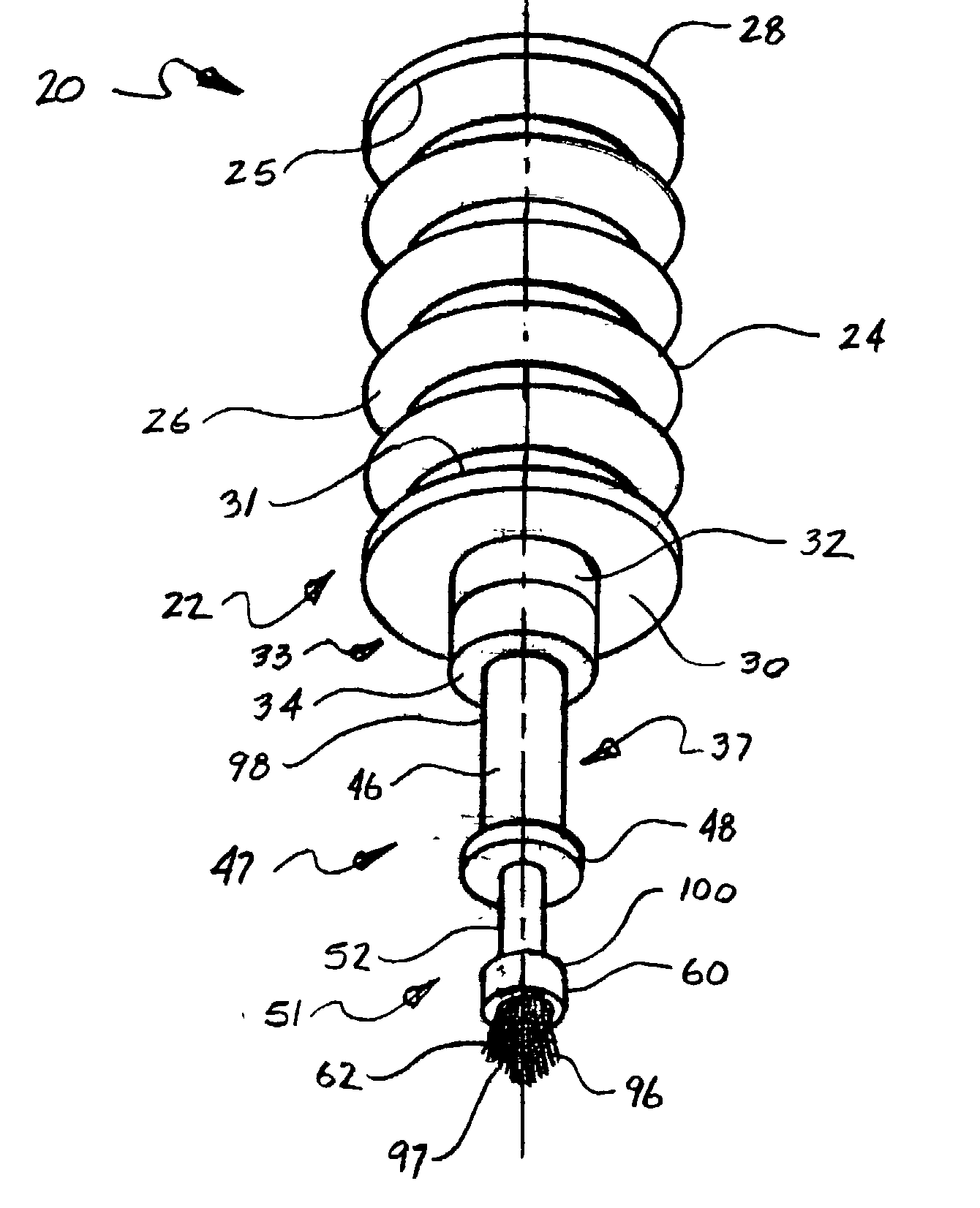
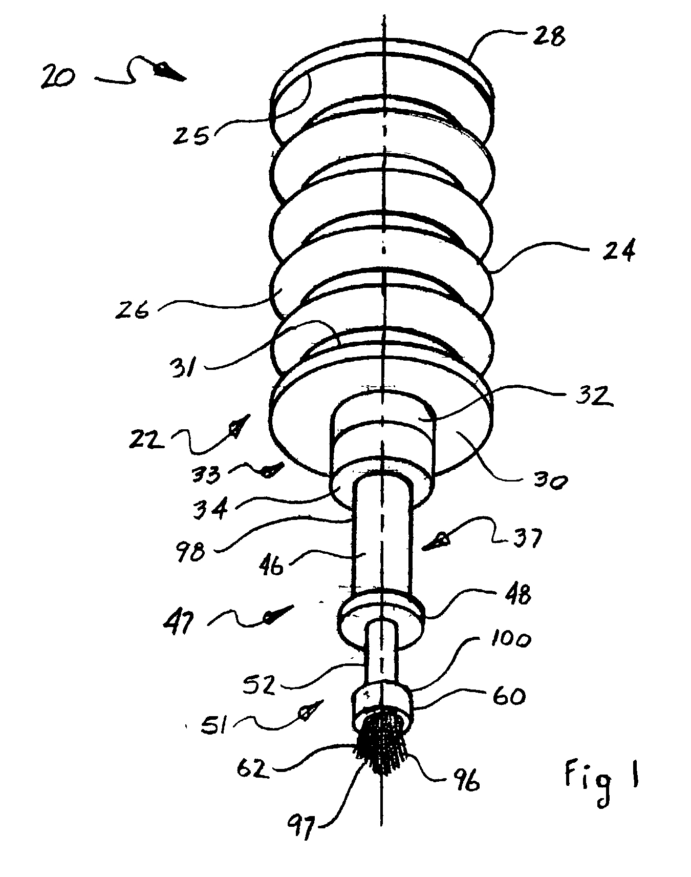
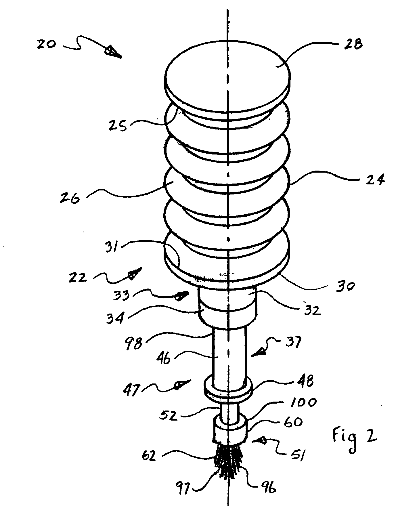
[0098] With initial reference to FIGS. 1 and 2, FIG. 1 shows a perspective view of the fluid dispenser 20 assembly from the applicator 47 side and FIG. 2 shows a perspective view of the fluid dispenser assembly 20 from the first end sealing cap 28 side. The fluid dispenser 20 is designed to allow the user to manually apply a selected fluid to a desired location by the user and comprises two major elements, being a reservoir assembly 22 and the applicator assembly 47. The reservoir assembly 22 that is able to contain the selected fluid includes a resilient body portion 24 that has a resilient body portion first end 25 and a resilient body portion second end 31. The reservoir assembly 22 also includes a first end sealing cap 28 and a second end sealing cap assembly 33 that includes a second end-sealing cap 30 that acts in conjunction with the resilient body portion 24 to define a reservoir interior that is not shown in FIGS. 1 and 2. The resilient body portion 24 has a bellows 26 that...


PUM


Abstract

A fluid dispenser and method for applying a selected fluid to a desired location includes a reservoir containing the fluid, the reservoir includes a resilient body having a first end and a second end, a first end sealing cap, and a second end sealing cap assembly with a penetrable elastomeric member to define a reservoir interior. The body includes bellows oriented to retract or extend the body between the first end and the second end creating a variable reservoir interior volume. Also included is an applicator having a proximal end and a distal end, the proximal end includes a non coring cannula with a lumen having an insertion end adapted to penetrate through the elastomeric member and protrude into the reservoir interior. This enables fluid communication between the reservoir interior and the lumen; the distal end also includes an application element that is in fluid communication with the lumen.

Description

[0001] The present invention generally relates to fluid dispensing apparatus and more particularly to a portable manually operated fluid dispenser and applicator for the selective application of a specific fluid to a desired location.BACKGROUND OF INVENTION[0002] There are a variety of fluid dispensers in the prior art. Fluid dispenser components typically comprise: a reservoir, a means for regulating fluid flow, and an applicator. The reservoir contains a fluid and also has a means for motivating the fluid to communicate into the means for regulating the fluid flow and further communicating to the applicator. The means for motivating the fluid out of the reservoir can be anything from simply using gravity to having a means for increasing the pressure of the fluid in the reservoir thus motivating the fluid to flow out of the reservoir through the means for regulating the fluid flow and onward to the applicator. The means for motivating the fluid out of the reservoir outside of simpl...

Claims


Application Information

Patent Timeline
IPC IPC(8): A45D34/04A46B11/02B43L25/00B43L25/04B43M11/06B65D1/02B65D47/42
CPCA45D34/042A45D34/045A45D2200/1018B65D47/42B43L25/04B43M11/06B65D1/0292B43L25/007
Inventor KING, PATRICIA ANNE
Owner KING PATRICIA ANNE
Learn More