Earplug and method of manufacturing an earplug

a technology of earplugs and earplugs, which is applied in the direction of earplugs, ear treatment, etc., can solve the problems of devices, affecting the use of earplugs, and earplugs that are difficult to fully insert, so as to facilitate the handling of earplugs

Inactive Publication Date: 2004-03-11
CABOT SAFETY INTERMEDIATE CORP
View PDF16 Cites 68 Cited by
  • Summary
  • Abstract
  • Description
  • Claims
  • Application Information

AI Technical Summary

Benefits of technology

0016] In one embodiment of the invention, an earplug comprises a foam including an insertion portion for being inserted into an ear canal of a user and a skirt extending from the insertion portion. The skirt includes a receptacle formed at an interior thereof. The earplug further comprises a molded stem including a bonding portion which is received in the receptacle and a handle portion which extends from the receptacle. The handle portion facilitates handling of the earplug during manufacture and use thereof. The skirt extends around the bonding portion of the stem and the bonding portion and the foam are adhesively bonded in the receptacle.

Problems solved by technology

However, such earplugs and devices typically become uncomfortable over long periods of use.
However, foam earplugs of the roll-down type are often difficult to fully insert due to the pliable nature of such plugs.
That is, even in the rolled down state, the plug still may not provide adequate rigidity to insert the body of the plug a sufficient distance into the ear canal.
Insufficient insertion results in inadequate attenuation and is thus undesirable.
Mechanically bonding the foam and stem as described is a difficult and often inconsistent process.
However, the individual porous stems are relatively expensive and somewhat difficult to manufacture and proper venting is often not attained.
Again, such additions to stems and molds are costly and their effectiveness in properly venting the mold is often found to be insufficient.
However, an insufficient bond is often formed between the foam and stem when utilizing this process.
Further, such process is messy, labor intensive, time consuming, and costly, thus not presenting a suitable means for automated mass production of stem component foam earplugs.

Method used


Image

  • Earplug and method of manufacturing an earplug
  • Earplug and method of manufacturing an earplug
  • Earplug and method of manufacturing an earplug

Examples


Embodiment Construction

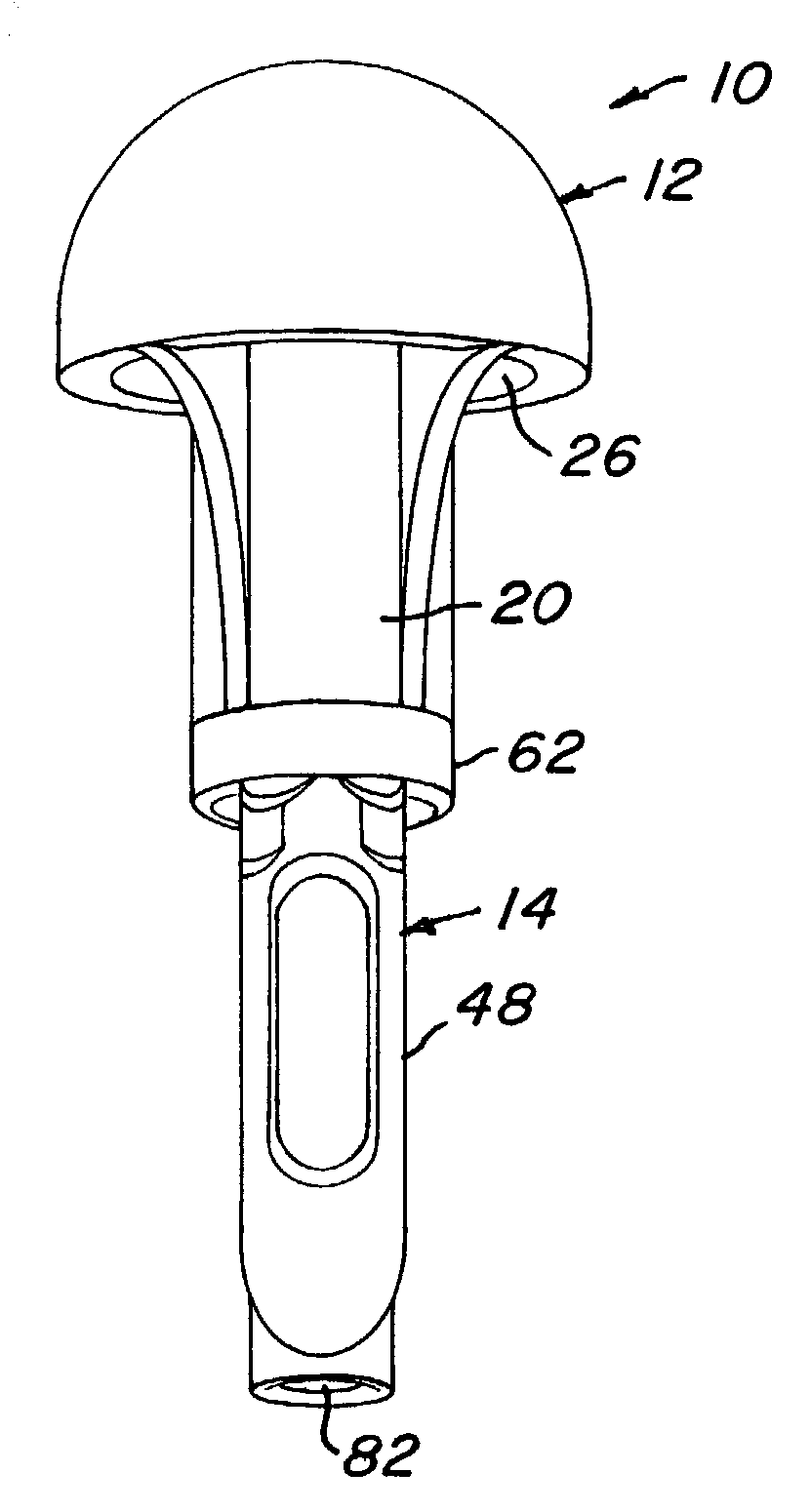
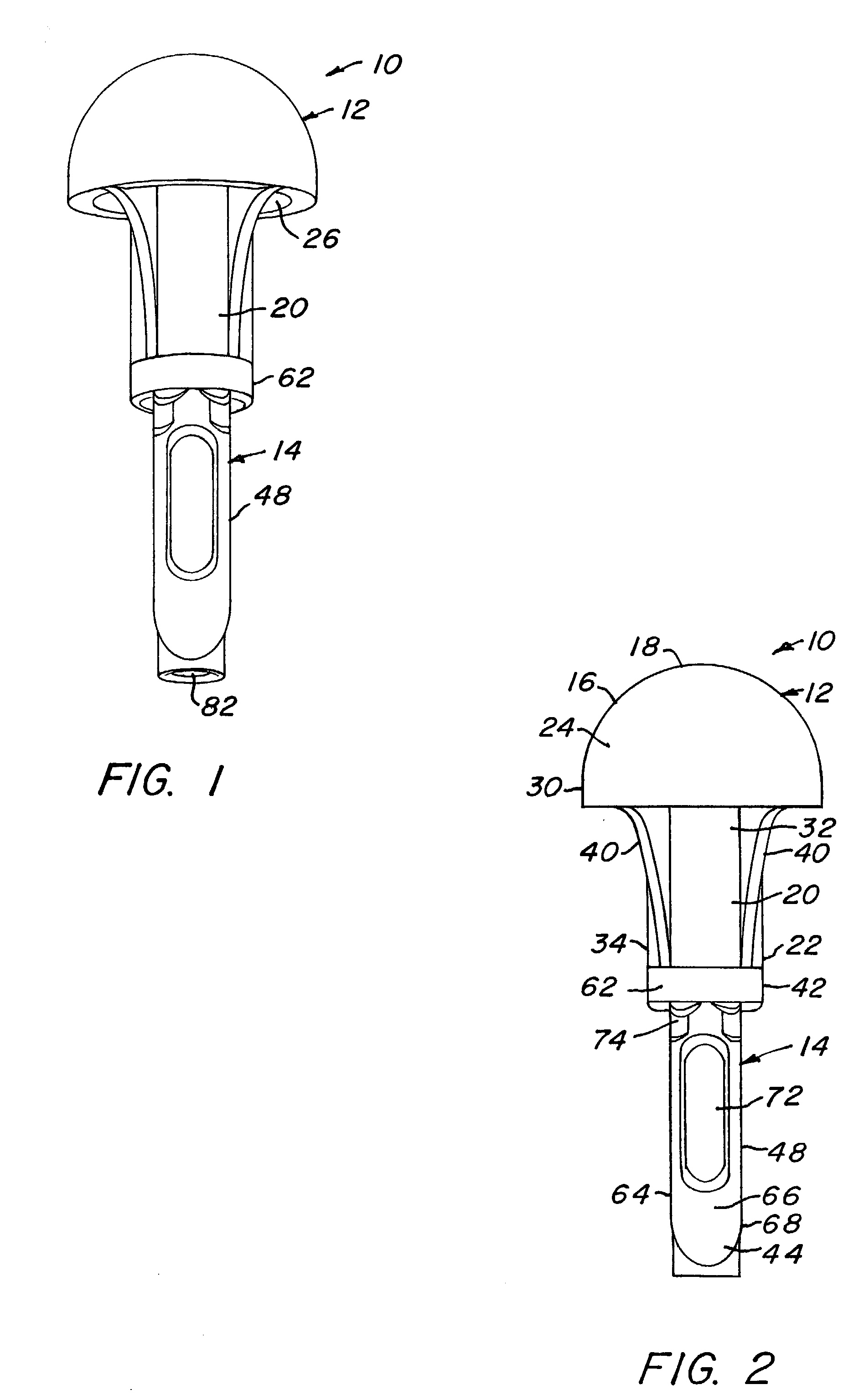
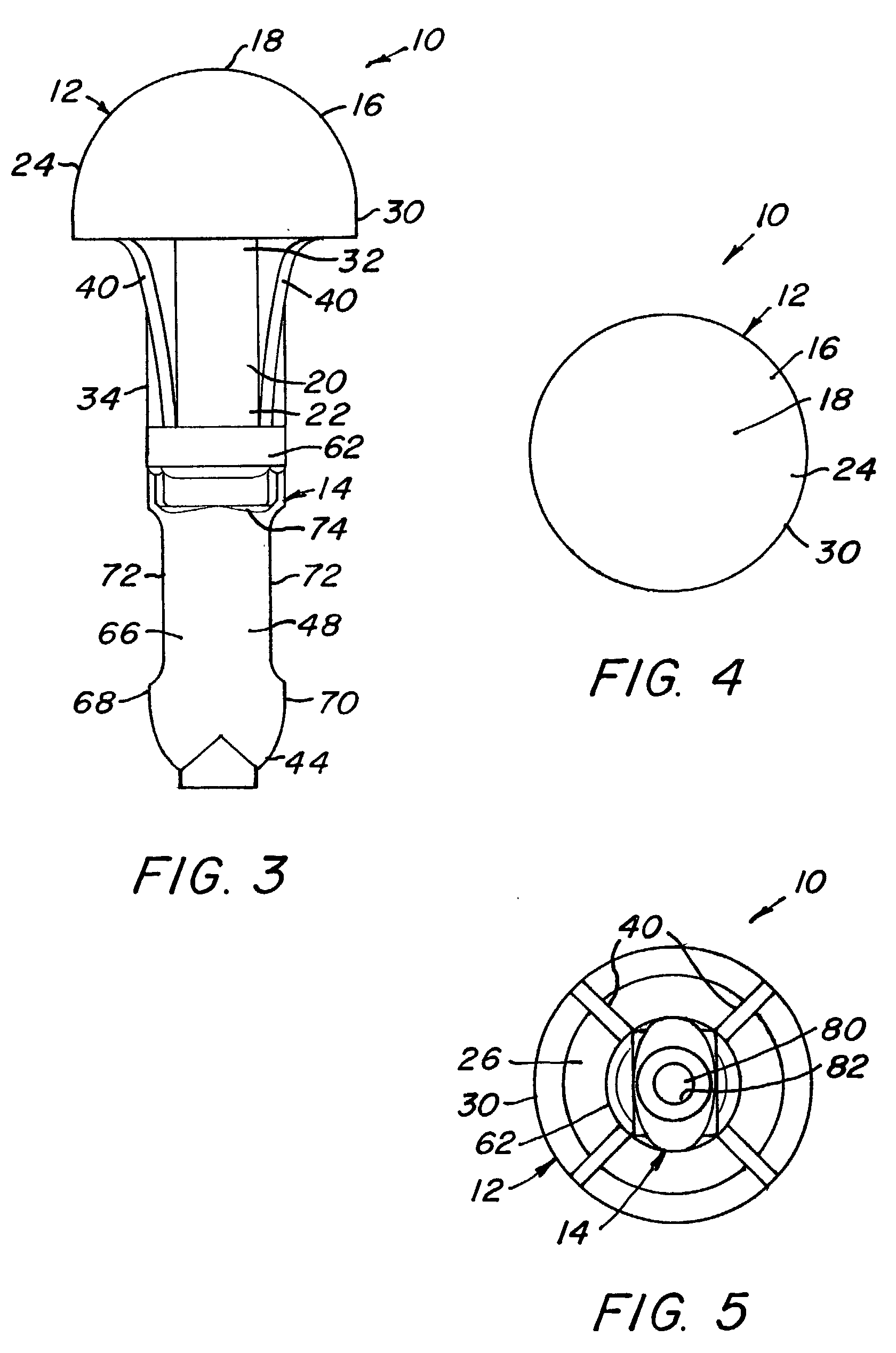
[0035] FIGS. 1-5 show various views of an earplug 10 in one embodiment of the invention. The earplug 10 includes a foam 12 and a stem 14. The foam 12 includes a rounded portion 16 at a first end 18 of the foam 12 and a skirt 20 at an opposite second end 22 of the foam 12.

[0036] The rounded portion 16 has a substantially semi-hemispherical shape and includes a rounded surface 24 formed proximate the first end 18 of the foam 12 and a concave surface 26 disposed opposite the rounded surface 24. The rounded and concave surfaces 24 and 26, respectively, give the rounded portion 16 a generally crescent shaped axial cross-section (FIG. 7). As such, an edge 30 is formed at an interface between the rounded and concave surfaces 24 and 26, respectively. The edge 30 comprises essentially a flap of the rounded portion 16 is pivotably movable relative to a longitudinal axis of the earplug 10. This feature provides comfort and ensures a proper fit when the earplug 10 is inserted into an ear canal ...


PUM


Abstract

An earplug and a method of manufacture thereof is provided, the earplug includes a foam having an insertion portion for being inserted into an ear canal of a user and a skirt extending from the insertion portion. The skirt includes a receptacle formed at an interior thereof. The earplug further includes a molded stem having a bonding portion which is received in the receptacle and a handle portion which extends from the receptacle. The handle portion facilitates handling of the earplug during manufacture and use thereof. The skirt extends around the bonding portion of the stem and the bonding portion and the foam are adhesively bonded in the receptacle.

Description

BACKGROUND OF INVENTION[0001] (1) Field of Invention[0002] The present invention relates generally to hearing protective devices, and more particularly to an earplug including an injection molded stem adhesively bonded to a foam.[0003] (2) Description of Related Art[0004] The use of hearing protective and noise attenuating devices is well known, and various types of devices are available including semi-aural devices and earplugs. Foam components are well known for use with these devices, providing both sound attenuation and enhanced comfort for the wearer.[0005] Earplugs are generally utilized for continuous use over longer periods of time. Foam earplugs composed of resilient polymer foam materials such as foam rubber or polyurethane are well known in the art. Slow recovery foam earplugs, such as those disclosed in U.S. Reissue. No. 29,487 to Gardner, Jr., provide comfort and have also been shown to deliver high in-field noise protection at all frequencies. U.S. Pat. No. 5,203,352 t...

Claims


Application Information

Patent Timeline
Patent Type & Authority Applications(United States)
IPC IPC(8): A61F11/08
CPCA61F11/08
Inventor TAYLOR, DUNCANKLUN, BOB
Owner CABOT SAFETY INTERMEDIATE CORP
Why Eureka
Try Eureka