Creep and viscous flow resistant fiber optic sensor

a fiber optic sensor, viscous flow technology, applied in the direction of fluid pressure measurement, fluid pressure measurement by electric/magnetic elements, instruments, etc., can solve the problems of sensor gap length, sensor gap length, and unpredictably altered tube geometry to maintain sensor gap length

Inactive Publication Date: 2004-03-11
VIRGINIA TECH INTPROP INC
View PDF16 Cites 19 Cited by
  • Summary
  • Abstract
  • Description
  • Claims
  • Application Information

AI Technical Summary

Problems solved by technology

However, this structure presents two points of potential instability: the bond of the glass tube to the optical fibers and the glass tube, itself.
On the other hand, Fused silica glass is known to be subject to viscous flow when subjected to even small forces over an extended period of time which can change the geometry of the tube in a direction tending to relieve forces thereon and, consequently, the sensor gap length.
These voids may spontaneously collapse over time in a process referred to as volume consolidation and which can be accelerated by temperature and / or pressure; resulting in unpredictably altered geometry of the tube relied upon to maintain sensor gap length.
Consider that a small but persistent change occurs over time in the geometry of the glass tube in a basic fiber optic sensor as described above resulting in a slight shortening of the tube and the gap by an unknown amount.
However, current applications of interest may involve telemetry from a well which may have a depth of several miles, economically precluding removal from service and recalibration except on a very infrequent basis.
At the same time, extremely harsh and continuous conditions of increased temperature, pressure and / or strain encountered in such applications have been found to substantially accelerate both viscous flow and volume consolidation in sensors of conventional sensor construction such that significant errors and drift may occur under tensile loading over as short a period as several weeks; a much shorter period than is economically feasible for removal and recalibration of a sensor so deployed.
It is to be expected that similar effects will occur in comparable degree under compressive loading, as well, and may be even less predictable, particularly at the point that substantially full densification is reached through volume consolidation.
Further, no technique for in-situ recalibration has been devised to date or is anticipated since the conditions of interest cannot generally be removed or artificially varied while the sensor remains in place.
The problem of viscous flow and volume consolidation of the fused silica or other material in fiber optic sensors is not limited to tube-based sensors but, in general, the problem will extend to any other types of sensors using fused silica or other material having similar attributes of viscous flow and / or volume consolidation, depending on the criticality of the dimensional stability of the component in which fused silica is used and the criticality of the measurement to be made.
As such, tube-based sensors, diaphragm-based sensors, V-groove sensors and the like, will all suffer the same problem as long as they include elements made of glass.

Method used


Image

  • Creep and viscous flow resistant fiber optic sensor
  • Creep and viscous flow resistant fiber optic sensor
  • Creep and viscous flow resistant fiber optic sensor

Examples


Embodiment Construction

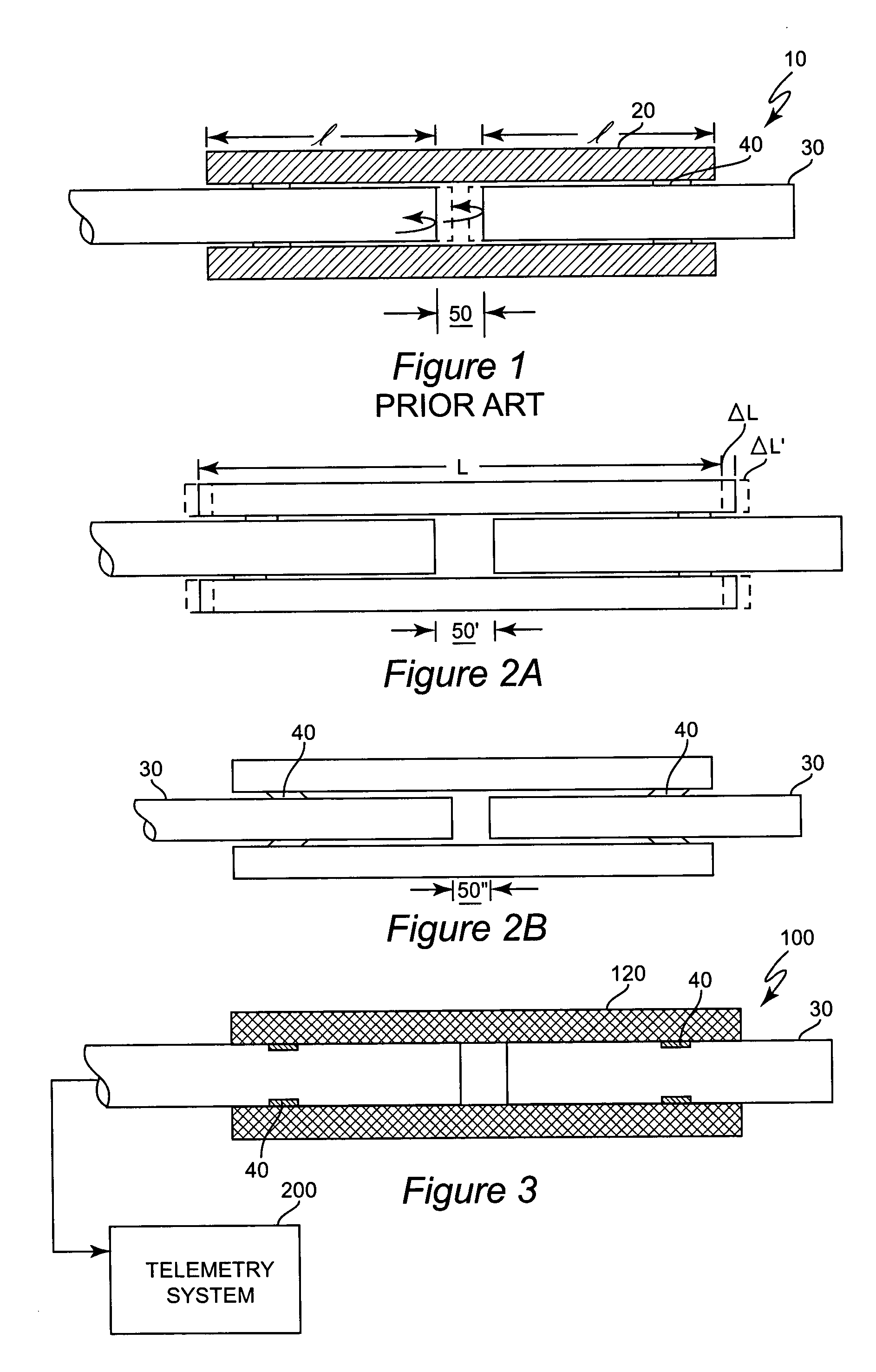
[0022] Referring now to the drawings, and more particularly to FIG. 1, there is shown a conventional structure of a fiber-optic sensor 10. As alluded to above, the body of the sensor is formed of a fused silica tube 20. A length of fiber optic material 30 is inserted in each end of the tube and fixed in position by bonds 40 which are preferably of short length along the tube but may be placed at any location along length l. In general, a greater separation of the bonds 40 will favor sensing of strain or together with a large differential of coefficients of thermal expansion (CTE) between the fiber optic material and the tube material will favor sensing of temperature (e.g. relative to pressure) while a good match of CTE and reduced separation will favor sensing of pressure relative to strain and temperature. That is, by adjustment of the geometry and material properties, relative sensitivities of the length of gap 50 to strain, temperature and pressure may be altered at will within ...


PUM


Abstract

Viscous flow and volume consolidation which may cause sensor output drift are avoided in a fiber optic sensor by using a body of crystalline and preferably monocrystalline material to establish the transducer gap. Use of a monocrystalline material also reduces chemical reactivity of the sensor with substances which may be present where the sensor is deployed. The increased dimensional stability of the monocrystalline body in a tube-based, V-groove-based or other type of fiber optic sensor reduces the need for and frequency of recalibration.

Description

[0001] This application claims priority of U. S. Provisional Patent Application Serial No. 60 / 407,981, filed Sep. 5, 2002, entitled "Creep and Viscous Flow Fiber Optic Sensor" which is hereby fully incorporated by reference.[0002] 1. Field of the Invention[0003] The present invention generally relates to fiber optic sensors for measuring parameters such as temperature and pressure and the like and, more particularly, to fiberoptic sensors which resist long-term effects of temperature and pressure and which may thus be allowed to remain in service for long periods without need for recalibration.[0004] 2. Description of the Prior Art[0005] Fiber optic sensors have been known for a number of years and are much preferred for making remote measurements of temperature, pressure and other conditions such as strain, flow rate, shear forces and the like, particularly in harsh environments. Performing telemetry using radiant energy carried by fiber optic light guides is inherently free from e...

Claims


Application Information

Patent Timeline
Patent Type & Authority Applications(United States)
IPC IPC(8): G02B6/34G02B6/36G02B6/38
CPCG01D5/268G01L9/0079G02B6/3854G02B6/3624G02B6/29359G01D5/35312
Inventor PICKRELL, GARY R.WANG, ANBO
Owner VIRGINIA TECH INTPROP INC
Why Eureka
Try Eureka