Wafer lifting device

a lifting device and wafer technology, applied in the field of wafer lifting devices, can solve the problems of unfavorable point-type exposure of wafers to heat, unsatisfactory pin guidement, and extremely undesirable generation of particles

Inactive Publication Date: 2004-03-18
POLARIS INNOVATIONS
View PDF4 Cites 7 Cited by
  • Summary
  • Abstract
  • Description
  • Claims
  • Application Information

AI Technical Summary

Problems solved by technology

However, such point-type exposure of the wafer to heat is unfavorable for technological reasons.
Such a wafer lifting device has the disadvantage that the pins cannot be guaranteed to be guided entirely satisfactorily on account of the thermal expansion between the through holes.
This has the effect that the pins may rub in the through holes, w

Method used


Image

  • Wafer lifting device
  • Wafer lifting device
  • Wafer lifting device

Examples


Embodiment Construction

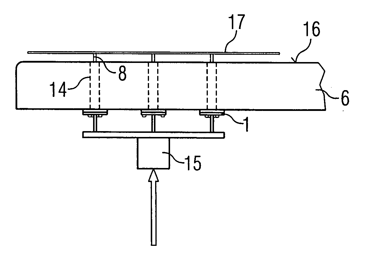
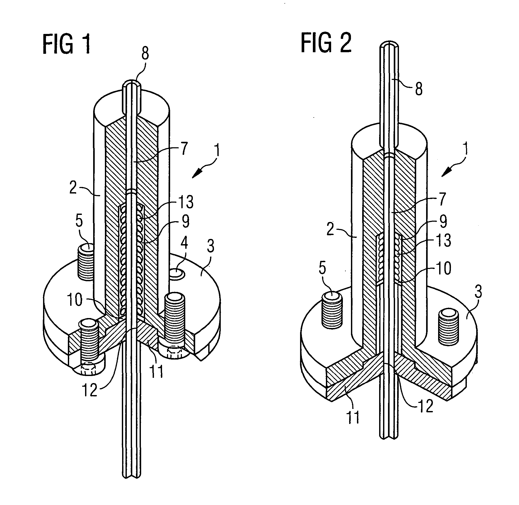
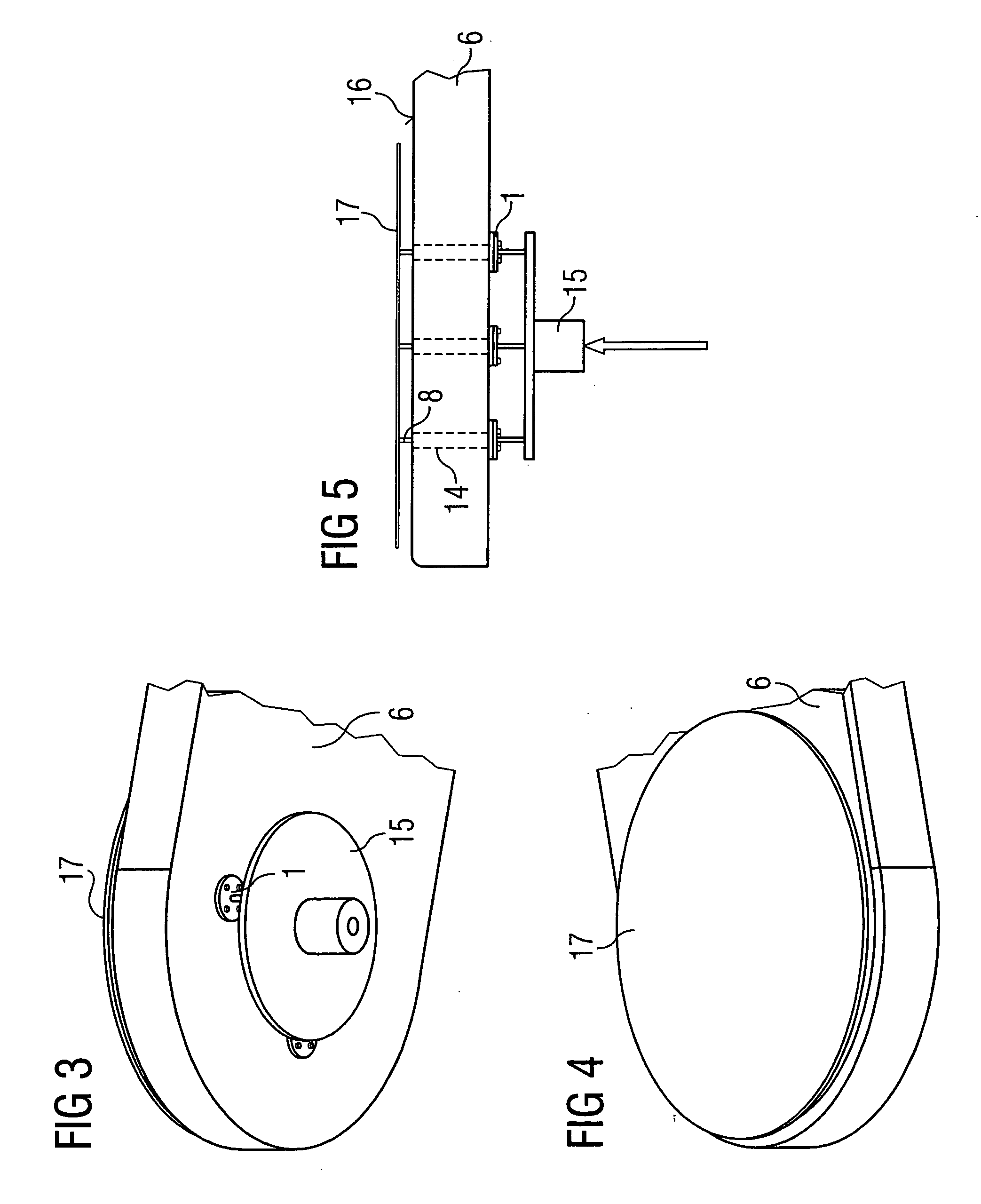
[0036] As illustrated in FIGS. 1 and 2, a pin guide 1 has a cylindrical body 2. The body 2 is provided with a flange plate 3 at its underside. The flange plate 3 is provided with fastening holes 4, through which fastening screws 5 can be screwed into threaded mounting holes in the wafer receptacle 6.

[0037] The cylindrical body 2 is provided with a guide hole 7, in which a pin 8 is arranged such that it can be moved longitudinally in smoothly running fashion. An enlarged bore 9 is formed in the body 2 coaxially with respect to the guide hole 7. In the enlarged bore 9, at the pin 8, an attachment 10 is arranged as a bead around the pin. At its lower end, the enlarged bore 9 is closed off with a cover 11, into which a pin guide hole 12 is formed coaxially with respect to guide hole 7 and enlarged bore 9, through which pin hole the pin 8 can be moved. The cover 11 forms the lower end of the enlarged bore 9.

[0038] A helical spring 13 surrounding the pin 8 is tensioned between the upper e...


PUM


Abstract

The invention, which relates to a wafer lifting device having a lifting platform arranged under a wafer receptacle, which lifting platform can be moved in the vertical direction and at least three pins which can be moved in through holes in the wafer receptacle. The pins are separately guided in the through holes. A pin is guided and held such that it can be moved longitudinally, and the pin guide is fixedly connected to the wafer receptacle.

Description

SPECIFICATIONBackground of the Invention[0001] The invention relates to a wafer lifting device having a lifting platform arranged under a wafer receptacle, the top side of which forms a wafer bearing area, wherein the lifting platform can be moved toward and away from the underside of the wafer receptacle, in a vertical direction. At least three pins extending in the vertical direction are arranged to move in through holes in the wafer receptacle, which run from the underside of the wafer receptacle to the wafer bearing area on the top side thereof. With the lifting platform raised, in a first upper position near the underside of the wafer receptacle, the pins project from the wafer bearing area by a selected amount. With the lifting platform lowered, in a second lower position remote from the underside of the wafer receptacle, the pins are retracted into the receptacle.[0002] It is known that, for fabricating semiconductor components with a wide variety of functions, chips are subj...

Claims


Application Information

Patent Timeline
IPC IPC(8): H01L21/687
CPCH01L21/68742
Inventor HUNGER, RUDIGERHERBERG, STEFFENBEDNARA, FALK
Owner POLARIS INNOVATIONS
Why Eureka
Try Eureka