Feed pipe coupling for a pressurised fluid system

a technology of pressurised fluid and feed pipe, which is applied in the direction of couplings, mechanical equipment, etc., can solve the problems of not being able to exert visual control, the coupling is not easy to connect in the locking position by the operator, and is not compatible with production requirements

Inactive Publication Date: 2004-03-18
VALEO EMBRAYAGES SAS
View PDF8 Cites 63 Cited by
  • Summary
  • Abstract
  • Description
  • Claims
  • Application Information

AI Technical Summary

Benefits of technology

[0032] Preferably, this geometry, with two branch portions of at least one of the branches of the spring clip, enables the stresses to be better distributed during its elastic deformation, and the stress level to be reduced. More precisely, the stresses are distributed essentially between the bent portion which joins the locking and connecting branch portions together, and the central connecting branch which joins the connecting branch portions together, and no longer at the level of a single bent portion joining the connecting portion to the two branches.
[0033] Thanks to the invention, the spring clip is more reliable and any risk of permanent residual deformation is removed, while preserving a spring clip which is small in size and inexpensive to make.
[0035] Preferably, the friction between the spring clip and the body takes place on the outer surfaces of the body so that no damage to the working surfaces of the body is likely to occur over time after repeated manoeuvres of the spring clip. In this way for example, the internal bore which plays a part in the guiding and sealing functions is preserved.
[0044] the spring clip is mounted on the body, in such a way that it cannot be lost, by stop means included in the body, which cooperate with the free end of at least one of the locking branch portions;

Problems solved by technology

The coupling is not easy to connect in its locking position by the operator, because it is necessary that the posterior first groove be in axial coincidence with the locking means.
secondly, a second rearward pulling force on the connector.
Now, since the operator is in no way able to exert visual control to obtain good positioning, he is obliged to feel his way, which is not satisfactory for various reasons.
Among these reasons may be mentioned the length of time which can be necessary for an operator to reach the purging position, and this is not compatible with production requirements, especially in the case where these fitting operations are carried out on motor vehicle production lines on which each operation must be as quick as possible.
These problems do of course occur as much to an operator during the initial fitting operation as, later on, during maintenance operations on the vehicle.
In this connection, when the operator has reached the position of having correctly located the second cylindrical portion, and can therefore axially disengage the connector towards the rear, it is still not possible for him to carry out the purging operation because he must first absolutely perform a second set of operations.
Apart from the fact that this second set of operations on the coupling has the same disadvantages as before, it does, more importantly, give rise to an additional safety problem.
Failing that, retention of the connector is not guaranteed, and under the action of the pressure in the fluid the connector runs the risk of being expelled violently out of the feed inlet body.
The reliability of such locking means is however not satisfactory.
There is therefore a risk that the locking portion will not correctly reposition itself in the groove of the head of the connector, which, because of the fluid flowing under pressure in the feed pipe coupling, renders the locking effect not as reliable as is desirable.
Without that, the main risk encountered is expulsion of the connector out of the body under the action of the pressure in the fluid.
These stresses give rise to residual deformation of the locking means, which is not entirely compensated for by their inherent elasticity, and this gives rise to the risk, as soon as the transverse branches are open too far radially outwards, that the locking portion will no longer be able reliably to ensure retention of the head of the connector in the body.

Method used


Image

  • Feed pipe coupling for a pressurised fluid system
  • Feed pipe coupling for a pressurised fluid system
  • Feed pipe coupling for a pressurised fluid system

Examples


Embodiment Construction

[0055] In the following description, in order to facilitate understanding, the expressions vertical, horizontal, anterior, posterior, left, right etc. will be used with reference to the Figures and in accordance with the definitions given in the description, but this is not to be taken as limiting.

[0056] In the description, those elements which are identical, similar or analogous to each other will be designated by the same reference signs.

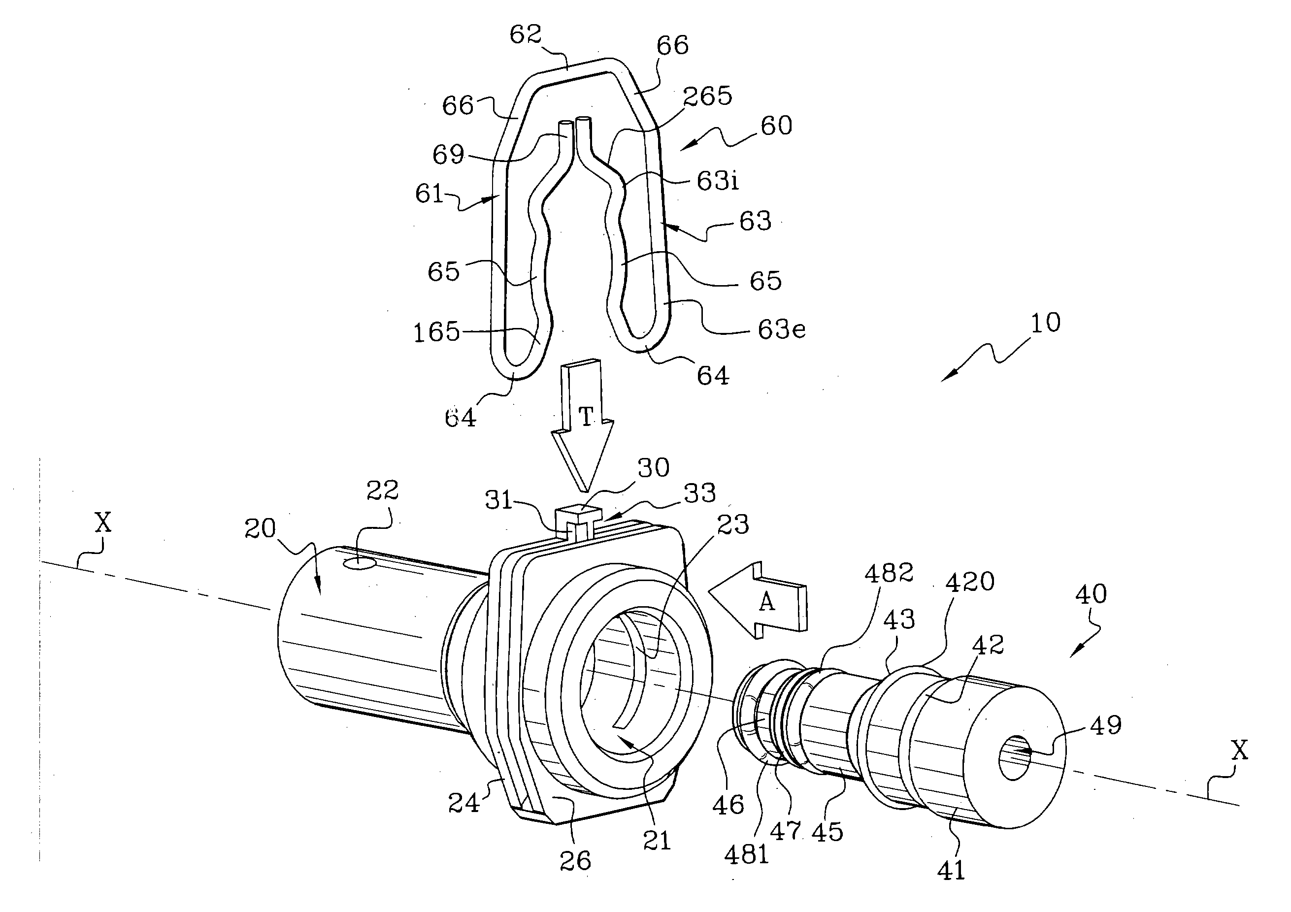
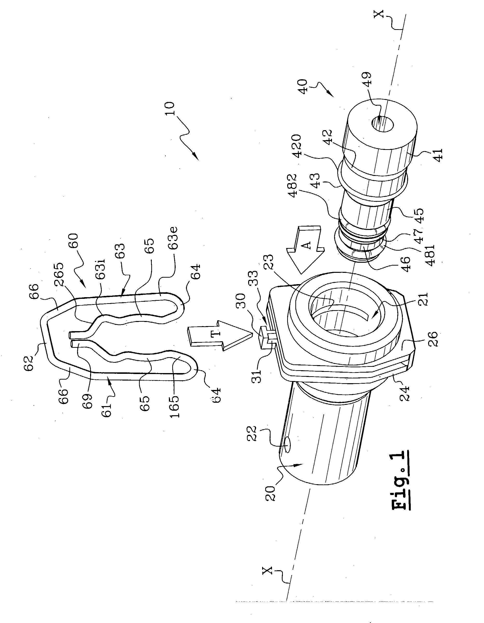
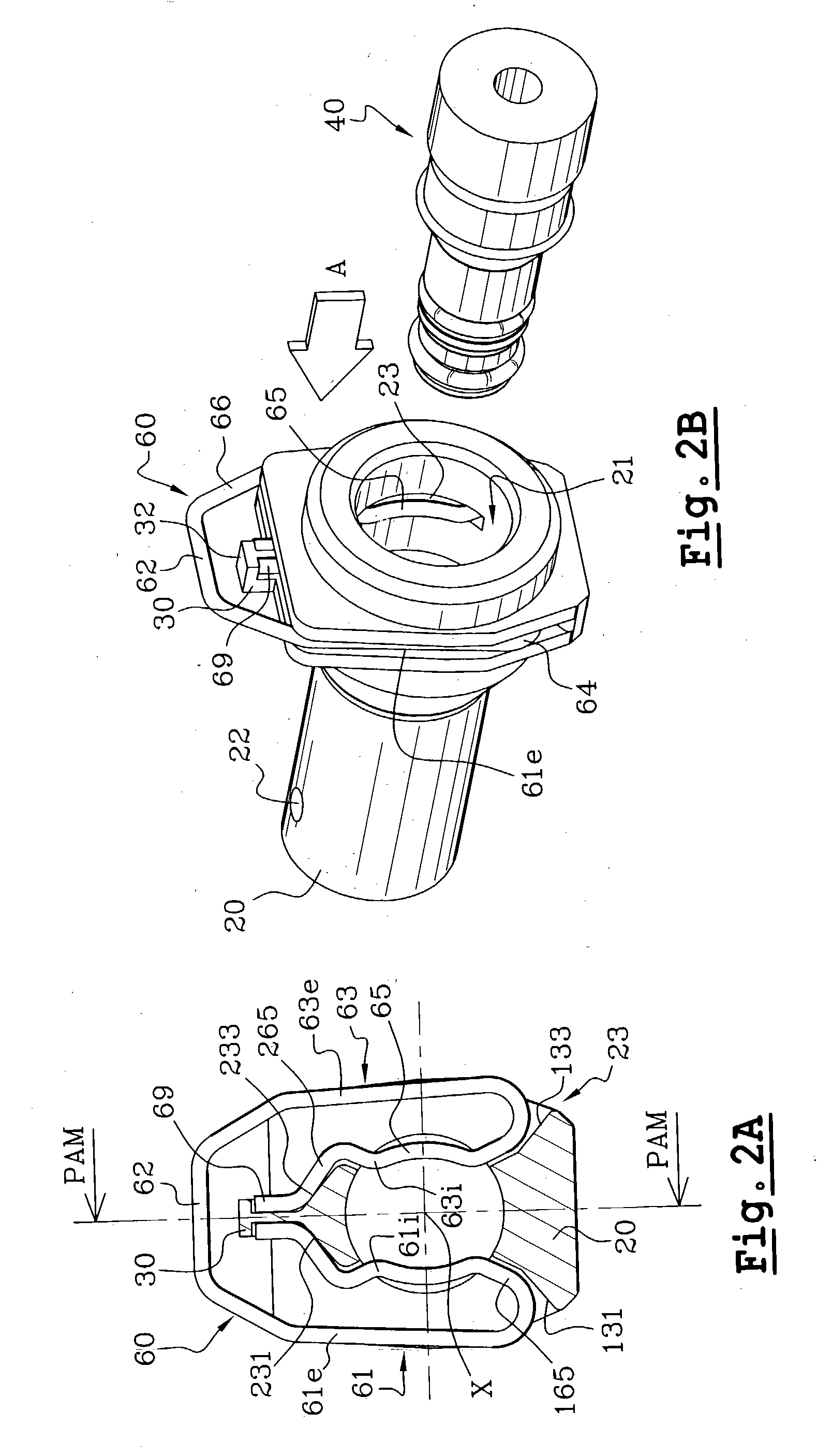
[0057] The feed pipe coupling for a pressurised fluid system, which is shown in FIGS. 1 to 6, consists essentially of: an anterior body 20 of a feed inlet 21, which in this example is substantially tubular on the axis X, and which may be fixed with respect to an hydraulic device such as an emitter or a receiver (not shown); a posterior connector 40 which is arranged to be fixed to the end of a feed pipe (not shown); and locking means 60 interposed between the connector 40 and body 20 so as to secure them together.

[0058] It is chosen to describe th...


PUM


Abstract

The invention proposes a feed pipe coupling for a pressurised fluid system, characterised in that the branch of the spring clip which includes the locking portion is configured generally as a hairpin having a radially internal, locking, first branch portion of which the locking portion is a part, together with a radially external, connecting, second branch portion which is connected at each of its ends, firstly to the operational locking branch portion through a bent connecting portion, and, secondly to the central connecting branch of the spring clip, in such a way as to give the locking branch a capacity for elastic deformation in the general transverse plane of the spring clip.

Description

[0001] This invention relates to feed pipe couplings for pressurised fluid systems, especially for application to a motor vehicle. More particularly, the invention relates to a feed pipe coupling for a pressurised fluid system, of the type in which a connector has a head which is adapted to be received axially in a body of a feed inlet, and of a type in which the connector is adapted to be locked in a forward position in which it is engaged axially in the feed inlet body by locking means.[0002] It is known to make use of couplings of the above type, also referred to as releasable couplings, in order to enable a feed pipe to be connected in a simple and inexpensive way on the inlet of an item of hydraulic equipment. Such a feed pipe connector for a pressurised fluid system is for example known from the document FR-A-2 736 136.[0003] That document describes, more particularly, a coupling of the type in which a connector is adapted to be held in a position in which it is engaged, axial...

Claims


Application Information

Patent Timeline
Patent Type & Authority Applications(United States)
IPC IPC(8): F16L37/14
CPCF16L37/088F16L37/0885F16L37/14
Inventor TROUYET, REMI
Owner VALEO EMBRAYAGES SAS
Why Eureka
Try Eureka