Stent with combined distal protection device

a protection device and distal protection technology, applied in the field of stents with combined distal protection devices, can solve the problems of patient death and permanent injuries

Inactive Publication Date: 2004-03-18
LEE DON W
View PDF5 Cites 69 Cited by
  • Summary
  • Abstract
  • Description
  • Claims
  • Application Information

AI Technical Summary

Benefits of technology

[0014] Another object of the invention is to provide an apparatus of the aforementioned character which includes a uniquely designed stent delivery catheter having a central lumen through which a guide wire travels, the central lumen being provided with a valve means that is operable by the guide wire and when moved into a closed position by withdrawal of the guide wire functions to prevent bloodflow toward the proximal end of the catheter.
[0018] By way of summary, the present invention provides a method and apparatus for preventing embolic material from escaping a site of intervention within the carotid artery, the renal artery and like arteries. More specifically, the present invention provides an apparatus and method for introducing a stent into a region of a major blood vessel within the human body exhibiting plaque deposits, thereby opening the occlusion. The method and apparatus of the invention also prevents embolic material from traveling downstream within the blood vessel. Additionally, the apparatus of the invention includes a catheter of novel design that includes a central lumen provided with a uniquely designed check valve that, when moved into a closed position by withdrawal of the guide wire from the catheter lumen, substantially blocks the flow of blood and loose debris through the central lumen of the catheter in a direction toward the proximal end of the catheter.

Problems solved by technology

During the stent emplacement procedure, plaque that has been deposited on the walls of the vessel may be set free and when this material travels downstream, it can cause serious complications.
By way of example, loose embolic material released within the carotid arteries may travel downstream to the brain, possibly causing stroke, which can lead to permanent injuries and sometimes the death of the patient.

Method used


Image

  • Stent with combined distal protection device
  • Stent with combined distal protection device
  • Stent with combined distal protection device

Examples


Embodiment Construction

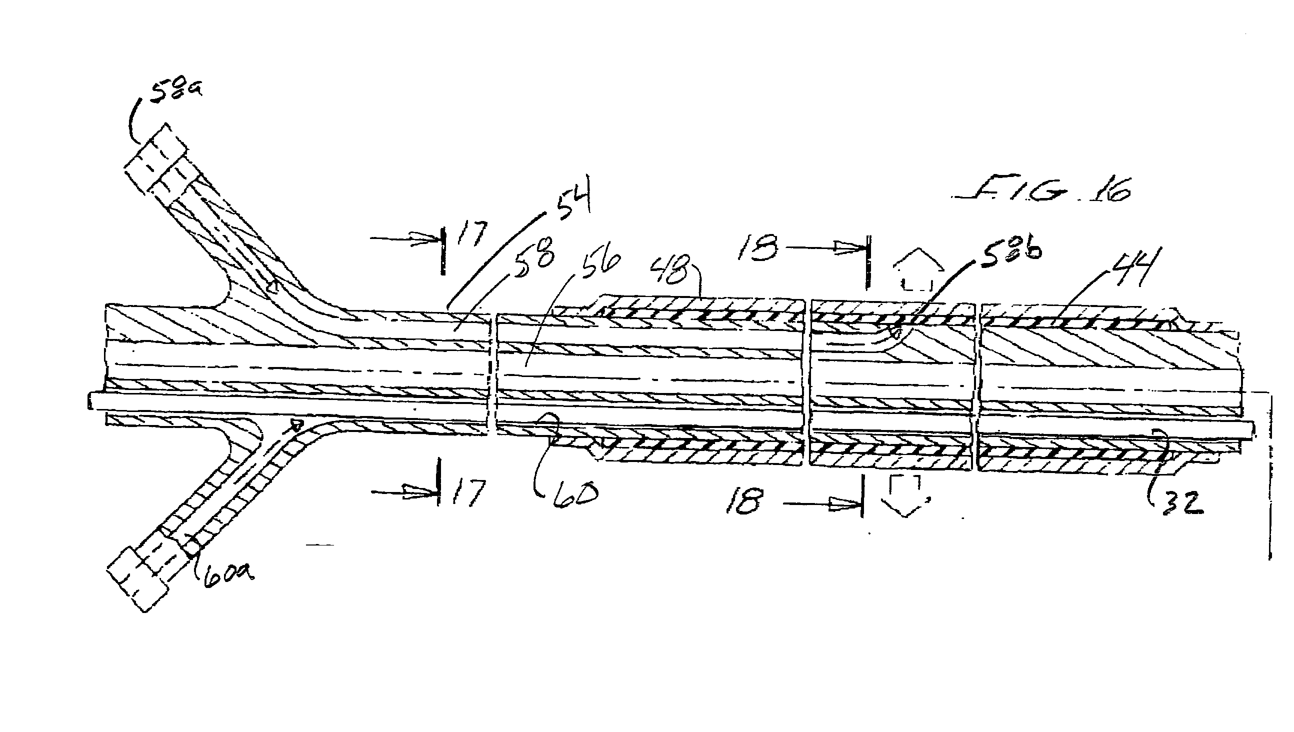
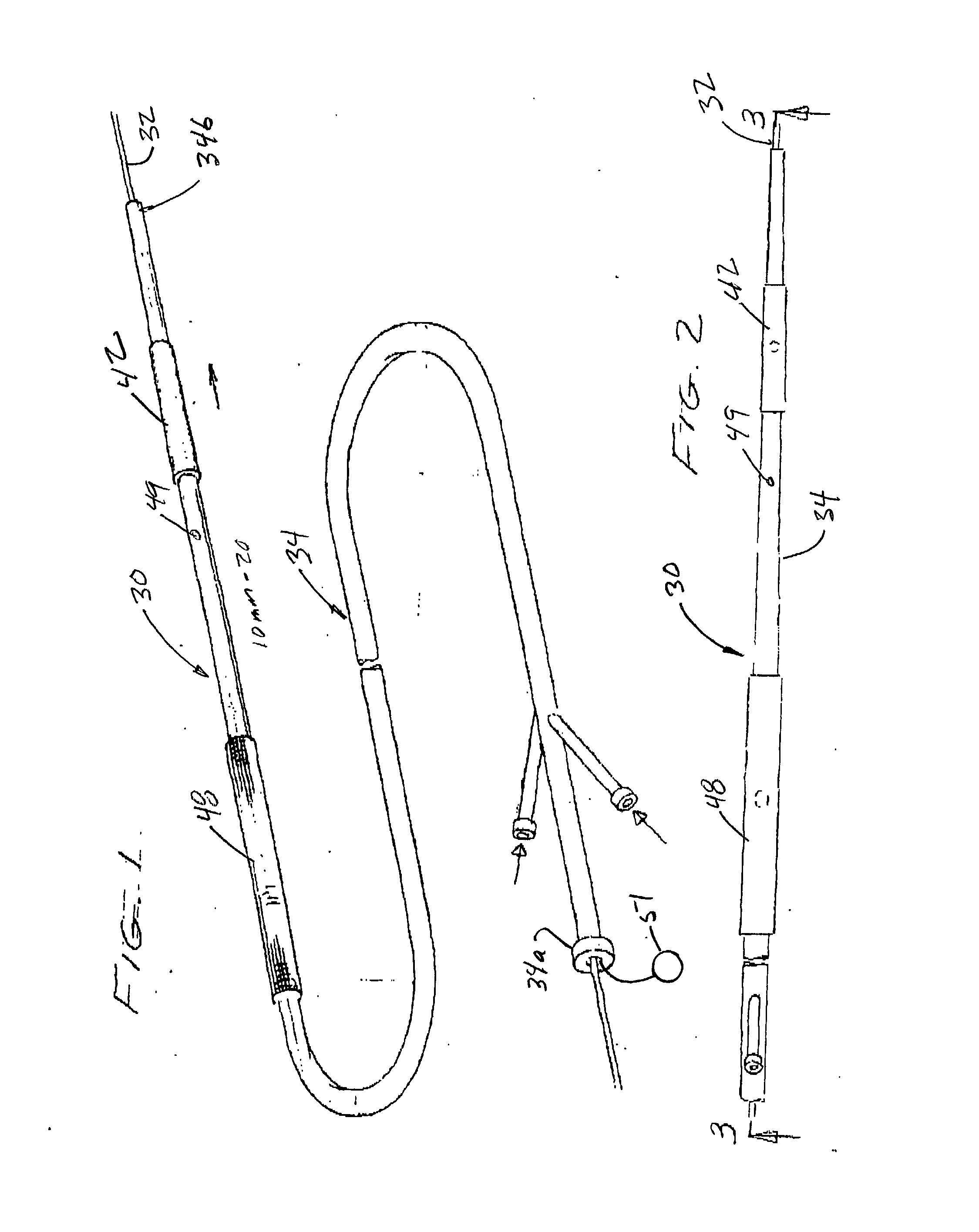
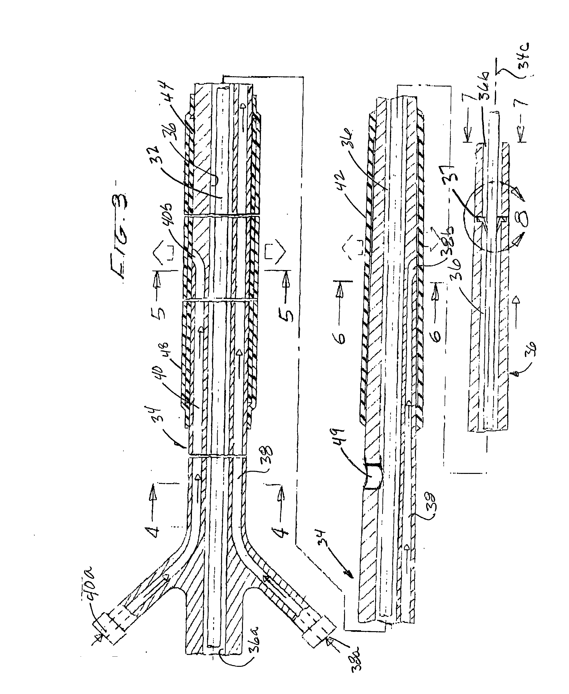
[0041] Referring to the drawings and particularly to FIGS. 1, 2 and 3, one form of the catheter system of the invention for balloon angioplasty and stent delivery is there illustrated and generally designated by the numeral 30. This system here comprises a guide wire 32 and an elongated catheter 34 having a proximal end 34a, a distal end 34b and an axial center line 34c. Catheter 34 is preferably formed of a biocompatible and hydrophilic compatible material, such as a lubricous polyimide or polyethylene. Other suitable materials for the catheter include nylons, urethanes, and polypropylene that are preferably compatible with coatings such as silicone and various hydrophilic coatings.

[0042] As is best seen by also referring to FIGS. 4, 5 and 6, in the present form of the invention, catheter 34 is provided with a first passageway 36 through which the guidewire 32 can be slideably moved. As illustrated in FIG. 3, first passageway 36 is coaxially aligned with axial center line 34c. By w...


PUM


Abstract

A method and apparatus for introducing a stent into a region of a major blood vessel within the human body in a manner which substantially reduces the risk of embolic material escaping to the vessel and causing a blockage at a downstream location. Additionally, the apparatus of the invention includes a uniquely designed stent delivery catheter having a central lumen through which a guide wire travels, the central lumen being provided with a valve means that is operable by the guide wire and when moved into a closed position by withdrawal of the guide wire, functions to prevent the flow of loose debris toward the proximal end of the catheter.

Description

[0001] 1. Field of the Invention[0002] The present invention relates generally to methods and apparatus for introducing a stent to into a region of a major blood vessel within the patient, such as the carotid artery, the renal artery and the coronary artery.[0003] 2. Discussion of the Prior Art[0004] A number of procedures have been suggested in the past for opening stenosed or occluded blood vessels in a patient caused by the deposit of plaque or other material on the walls of the blood vessels. For example, angioplasty, is a well known procedure wherein an inflatable balloon is first introduced into the occluded region and then inflated, dilating the stenosed blood vessel in the manner to increase the intraluminal diameter.[0005] Another well-known prior art procedure involves permanently or temporarily introducing a stent into the stenosed region to open the lumen of the vessel. The stent, which is readily commercially available from various sources, typically comprises a general...

Claims


Application Information

Patent Timeline
Patent Type & Authority Applications(United States)
IPC IPC(8): A61F2/06A61F2/84A61M39/06
CPCA61M39/0606A61F2/958
Inventor LEE, DON
Owner LEE DON W
Why Eureka
Try Eureka