Blow-molded container

a container and blow molding technology, applied in the field of blow molding containers, can solve the problems of cracking of the bottom seal, easy cracking of the outer layer at the bottom, and often found bottom cracking problems

Inactive Publication Date: 2004-04-01
YOSHINO KOGYOSHO CO LTD
View PDF2 Cites 9 Cited by
  • Summary
  • Abstract
  • Description
  • Claims
  • Application Information

AI Technical Summary

Problems solved by technology

Since the bottom seal has basically a laminated structure consisting of the outer layer and the inner layer, which are not compatible with each other, there was dissatisfaction in that the outer layer is easily cracked at the bottom.
However, in the above-described conventional art, there are cases of cracking in the bottom seal because of the effect of time-lapsed shrinkage at the bottom, which takes place after the containers have been blow-molded.
The problem of bottom cracking is often found especially in large-size containers of this conventional art when they are dropped to the floor or when they experience a shock.
A problem arises here because the bottom seal has large height, thickness, and cubic volume, which need long hours of cooling and thus result in quite low efficiency in the production of containers.
The inner container is provided with the first check valve that permits the content to pass through the valve and come out of the inner container but does not permit outside air to enter the inner container.
The outer container is provided with the second check valve that permits outside air to enter the void between both containers, but does not permit air to escape from the void.
Here is where problems arise.
A problem is that the adhered zone forms a rib that prevents uniform squeezable deformation.
Another problem is that the users feel strangeness in the touch with a hand.
Still another problem is that the adhesive resin used to form the adhered zone is expensive.
The formation of adhered zones causes irregularity on the outer surface of the body, and this irregularity is a process problem as well as the appearance problem.
Firstly, the technical problem of this invention is to achieve strong adhesion at the bottom seal between the outer layers and the inner layers, or between outer layers themselves by way of the inner layers, without increasing the bulk of the bottom seal.
Even if a good amount of content still remains in the entire inner container, there is a fear that the cross-sectional shape of the inner container may cause the flow path to be almost blocked at a place where the content tends to get smaller, depending on the condition of discharge from the vessel or on the condition of storage.
In this state, smooth discharge of the content is no longer possible.

Method used


Image

  • Blow-molded container
  • Blow-molded container
  • Blow-molded container

Examples


first embodiment

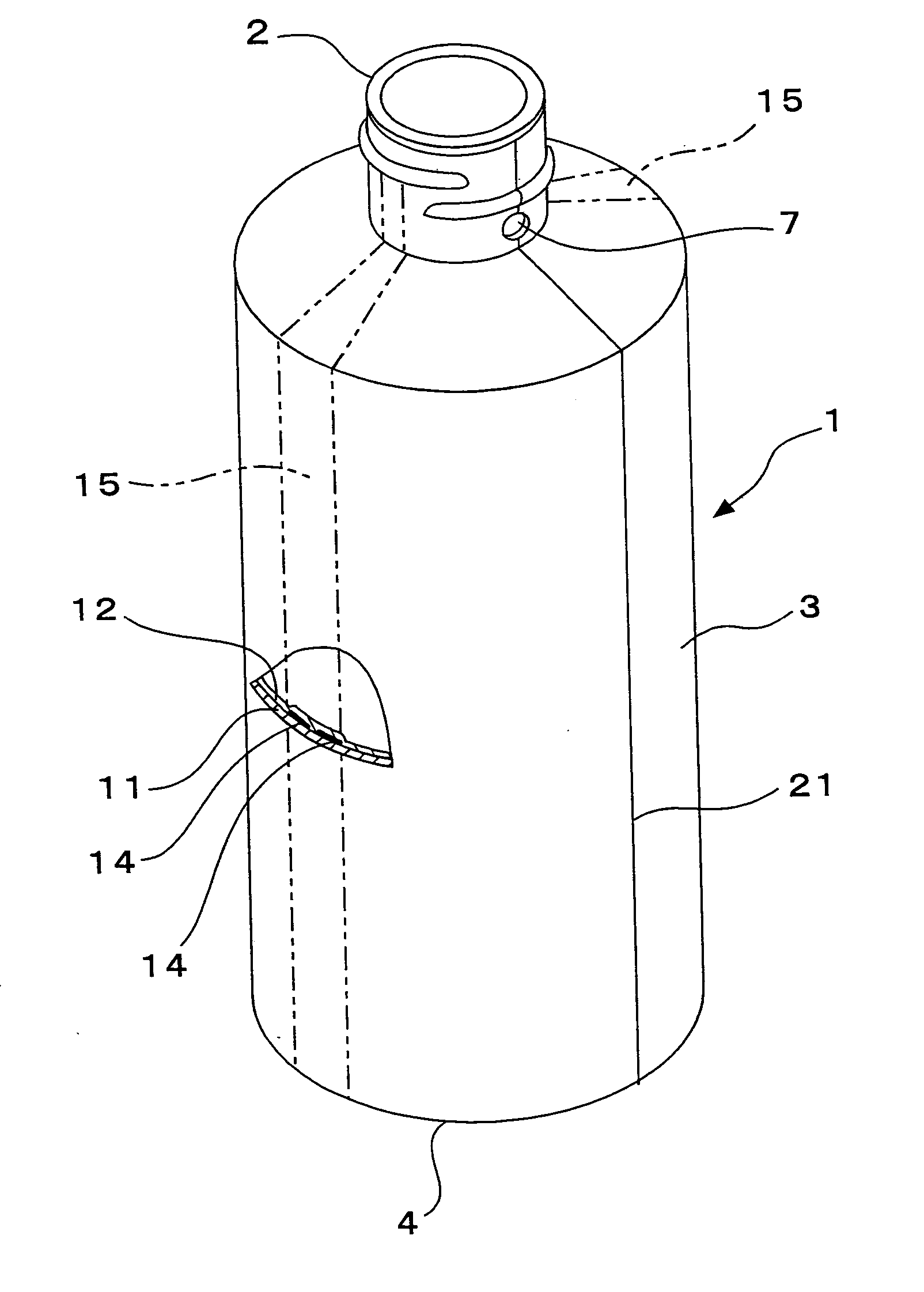
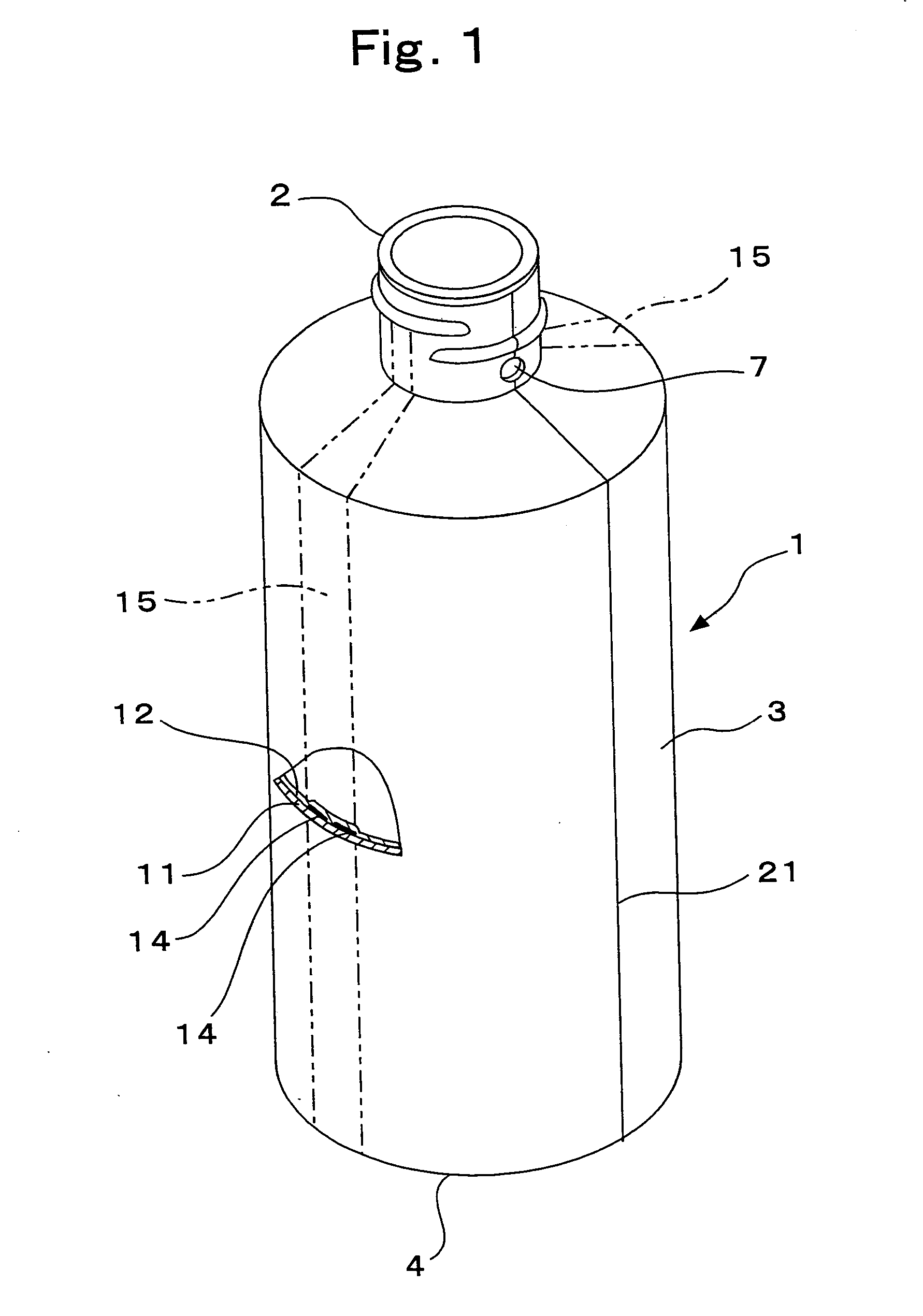
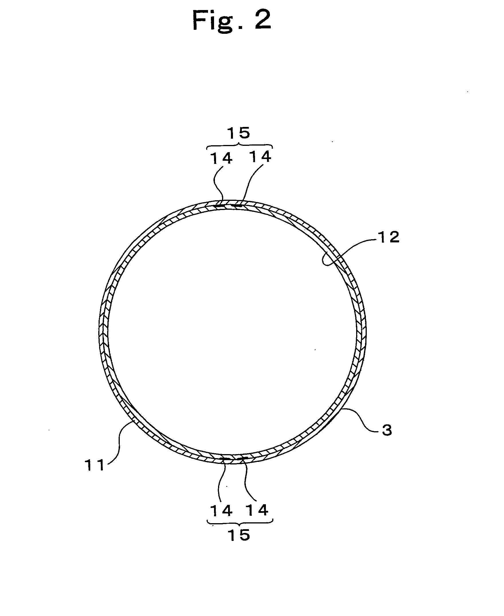
[0100] FIGS. 1-5 show the basic configuration of a blow-molded container in the first embodiment according to this invention. The container 1 is the blow-molded container comprising an outer layer 11 of a synthetic resin, such as polyethylene and polypropylene, which forms an outer shell having a necessary ability to maintain the shape of its own; an inner layer 12, which is molded into a flexibly deformable bag and is made of such a resin as nylon, ethylene-vinyl-alcohol copolymer, and polyethylene terephthalate, having no compatibility with the material of the outer layer 11; and the adhered zones 14 of the vertical strip type, which are disposed over the entire height of the container 1 and are made of an adhesive resin material that has full adhesiveness with both of the outer layer 11 and the inner layer 12. And a pair of restricted zones 15, each comprising a pair of or single adhered zones 14, is formed in the front and the rear of the container 1.

[0101] This container 1 has ...

second embodiment

[0120] When the container 1 in the second embodiment is blow-molded, the parison is set in the split blow mold at such a posture that two pairs of adhered zones 14 are put in the mold clamping direction taken from the central axis of the parison. As shown in FIG. 11, the adhered zones 14 reach the bottom seal 22 located on the parting line 21 of the bottom 4.

[0121] Two each of adhered zones 14, i.e., 14a1 and 14a2, or 14b1 and 14b2, are separated by the parting line 21 and are located opposite to each other. Thus, as shown in FIGS. 11 and 12, the lower ends of one pair of adhered zones 14 take the end-to-end positions facing those of the other pair of opposite adhered zones 14 in the central part of the pinched bottom seal 22 (hereinafter the portion in the end-to-end facing relationship between two adhered zones is referred to as the "end-to-end facing portion 24").

[0122] Therefore, as shown in FIGS. 13 and 14, the adhered zones 14 strongly adhere and fix the outer layers 11 on bot...

third embodiment

[0127] FIGS. 16, 18, 20, and 21 show the container 1 in this invention. The container 1 comprises an outer layer 11 of a low-density polyethylene resin, an inner layer 12 of a nylon resin that has no compatibility with the low-density polyethylene resin, and adhered zones 14 made of an adhesive resin that is fully adhesive with both of the low-density polyethylene and the nylon.

[0128] The bottle-like container 1 comprises the bottom 4, the body 3 having a circular cross-section, and the cylindrical neck 2 disposed on the upper end of the body 3 via shoulder and having screw thread notched around the outer surface of this neck 2.

[0129] The container 1 has a height of 160 mm. The body 3 has a circular cross-section and the diameter (bore diameter) of 60 mm.

[0130] The outer layer 11 and the inner layer 12, which make up the container 1, are laminated peelably except for the portions adhered and fixed by the adhered zones 14. The outer layer 11 forms the outer container 5 having a suffi...


PUM


Abstract

A blow-molded container of this invention comprises: an outer layer (11) of a synthetic resin, which forms the outer shell of a finite shape; an inner layer (12) of a flexible synthetic resin, which is peelably laminated with the outer layer (11) and forms an inner bag; and a pair of restricted zones (15) of a vertical broad strip type, which is formed axisymmetrically on the central axis of container (1) to adhere and fix the outer layer (11) and the inner layer (12) over the entire height and is located so as to avoid the positions of air introduction ports (7) that have been provided in the outer layer (11) to introduce air into the void between the outer layer (11) and the inner layer (12). At least one of the restricted zones (15) comprises two or more adhesive zones (14) of the vertical strip type, which are parallel to each other. In this configuration, a container of the delaminated type is provided, which has a sufficiently high mechanical strength at the bottom and which can be molded in an ordinary mold at a high rate of productivity. This invention also provides a container of the squeezable type, which has uniform, favorable squeezability, no strange feel to the touch, and a less deteriorated outer appearance caused by the provision of adhered zones.

Description

[0001] This invention relates to a peelably laminated, blow-molded container made of synthetic resins, which is obtained by peelably laminating an outer layer that forms an outer shell of a definite shape and an inner layer that forms a deformable inner bag, so that the content can be discharged and used without changing the outer appearance of this container.[0002] This invention also relates to a blow-molded container made of synthetic resins, which has been obtained by laminating peelably an inner container that can be deformed with the decrease in its content and a squeezable outer container, so as to enable the content to be discharged and used repeatedly without sucking up outside air into the inner container.[0003] Peelably laminated containers made of synthetic resins are known and obtained by peelably laminating an outer layer that forms an outer shell of a finite shape and an inner layer that forms a deformable inner bag. These blow-molded bottles are generally referred to...

Claims


Application Information

Patent Timeline
Patent Type & Authority Applications(United States)
IPC IPC(8): B65D1/02
CPCB65D1/0215Y10S215/902Y10S220/913
Inventor YONEYAMA, MASASHINAKAMURA, HIROYUKISEGUCHI, MASATOGOTO, TAKAYUKI
Owner YOSHINO KOGYOSHO CO LTD
Why Eureka
Try Eureka