Device and method for separation

a technology of separation device and separation method, which is applied in the direction of mechanical vibration separation, wet separation, water/sludge/sewage treatment, etc., can solve the problems of red blood cell deformation, difficult to obtain a complete separation of formed elements, and difficult manufacturing of certain angles

Inactive Publication Date: 2004-04-15
ERYSAVE
View PDF6 Cites 106 Cited by
  • Summary
  • Abstract
  • Description
  • Claims
  • Application Information

AI Technical Summary

Benefits of technology

[0014] The inventors have also realised the great importance of this idea. Because, according to the invention, the ultrasound source now do not have to be a part of the plane or layer where the channels reside, and space becomes available for packing more channels into a limited space, greatly enhancing the possibilities of manufacturing devices with a multitude of parallel channels providing high capacity particle separation. A high degree of particle separation could also easily be provided by a serial arrangement of separation units, as will be further explained below. The capability of high yield parallel and serial processing of a fluid using ultrasound is thus a central part and consequence of the inventive concept.
[0015] The above is possible because the channels and branching points are formed in a plate comprising one piece of material or in a few pieces of material closely bonded together. No special reflectors or the like are used. It may also be possible to use more than one ultrasound source. Thin dividers are arranged to separate the laminar flows after the branching points, thereby enhancing the effectiveness of the device. The device is preferably manufactured using silicon technology benefiting from the possibility of small precise dimensions, and the ultrasound energy could preferably be delivered by a piezoelectric element, which in turn could be driven from a control unit capable of delivering electrical energy of certain shape, frequency and power.

Problems solved by technology

However, certain angles can be difficult to manufacture with certain manufacturing processes.
One disadvantage with prior art in the form of centrifuges is that the red blood cells can become deformed, a disadvantage that is not present with a device according to the present invention.
A disadvantage is that it is very difficult to obtain a complete separation of the formed elements, instead a so-called "buffy coat" is obtained.

Method used


Image

  • Device and method for separation
  • Device and method for separation
  • Device and method for separation

Examples


Embodiment Construction

[0078] Take 100 ml blood with a haematocrit of 40%. This entails that 60% (=60 ml) of the blood is plasma. The plasma has a density of 1.0269. By adding 30 ml of 50% glucose solution we get according to the formula: 1 d tot = v 1 * d 1 + v 2 * d 2 v 1 + v 2

[0079] where

[0080] v.sub.1 is the volume of the first fluid

[0081] d.sub.1 is the density of the first fluid

[0082] v.sub.2 is the volume of the second fluid

[0083] d.sub.2 is the density of the second fluid

[0084] d.sub.tot is the density of the mix

[0085] The density of the mix medium becomes 1.0746.

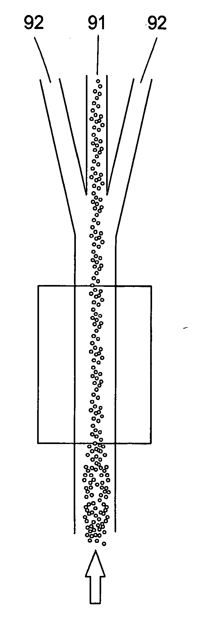
[0086] When this mixture is entered in an embodiment, a separation is achieved where thrombocytes and erythrocytes are directed into separate branches, because now the thrombocytes are lighter than the medium.

[0087] This is of course just an example. It is also possible to separate out leukocytes because they have a specific weight, different from the one of erythrocytes and thrombocytes. It should also be possible to separate out bacteri...


PUM

PropertyMeasurementUnit
angles α1aaaaaaaaaa
angles α1aaaaaaaaaa
thicknessaaaaaaaaaa

Abstract

The present invention provides a device and a method for separating particles from fluids using ultrasound, laminar flow, and stationary wave effects comprisinga micro-technology channel system with an integrated branching point or branching fork, and a single ultrasound source. One of the characteristics of the invention is that the single ultrasound source, which generates the standing waves, excites the complete structure including the channel system. No special reflectors or the like are needed. Extremely thin dividers can separate the flow, thereby enhancing the effectiveness of the device. The device could be manufactured in silicon and the ultrasound energy could preferably be delivered by a piezoelectric element.

Description

[0001] The present invention relates to a device and a method for separating a fluid containing suspended particles into fractions of higher and lower concentration of said suspended particles using ultrasonic standing waves and micro-technology.STATE OF THE ART[0002] It is known that when particles in a fluid are subjected to an acoustic standing wave field, the particles are displaced to locations at, or in relation to the standing wave nodes. A number of attempts to use ultrasound standing wave field for the manipulation or separation are known.[0003] In WO 00 / 04978 is described a device for performing the manipulation of particles suspended in a fluid. It comprises a duct for the flow of a fluid in which particles are suspended, and an acoustic transducer and a reflector for establishing an acoustic standing wave field across the width of said duct, the spacing between the transducer and reflector being 300 .mu.m or less.[0004] In an abstract to the 4.sup.th annual European conf...

Claims


Application Information

Patent Timeline
Patent Type & Authority Applications(United States)
IPC IPC(8): A61M1/34A61M1/36A61M1/02B01J19/00B03B5/00B03B5/02
CPCA61M1/3472A61M1/3479A61M1/3496A61M1/3678
Inventor LAURELL, THOMASALLERS, MATSJONSSON, HENRIKPERSSON, HANS WNILSSON, ANDREASPETERSSON, FILIP TOBIAS
Owner ERYSAVE
Why Eureka
Try Eureka