Method of assembling a single piece co-cured structure

a composite structure and co-curing technology, applied in the field of forming advanced composite materials, can solve the problems of complex structure, composite materials are often cost prohibitive, and composite materials are several times more expensive than metals or fiberglass

Inactive Publication Date: 2004-04-15
SPECTRUM AERONAUTICAL +1
View PDF27 Cites 70 Cited by
  • Summary
  • Abstract
  • Description
  • Claims
  • Application Information

AI Technical Summary

Problems solved by technology

However, composite materials also have some disadvantages.
Composite materials can be several times more expensive than metals or fiberglass.
Despite the desirable strength and weight characteristics of composite materials, the price of the composite materials can often be cost prohibitive.
Additionally, forming composite materials into a desired structure can require complex assembly equipment and multiple manufacturing procedures.
For example, composite materials often require expensive frames and mandrels in order to form a simple shape.
Additionally, these frames can require a complex resin injection system to impregnate the composite material with a resin.
Furthermore, once the composite materials are cured the attachment of multiple cured composite structures can be problematic.
Currently, most complex composite structures are manufactured by assembling multiple cured composite sections.
Each hole in the composite material severs fibers in the composite material, thus weakening the material.
However, both adhesive bonding and attaching traditional fasteners require time consuming assembly steps which are ultimately very expensive.
The expensive and complex steps for assembling a composite structure limit the widespread use of composite materials.
For example, one field where the disadvantages in composite materials restrict the widespread use is in the aeronautics field.
However, the advantages provided by composite materials in fuselage construction are often not beneficial enough to overcome the disadvantages.
For example, the high manufacturing costs of the fuselage can prevent the initial purchase of the aircraft, despite their lower fuel costs over a lifetime of operation.
Additionally, the multiple fasteners required to assemble the various sections of cured composite structures can reduce the strength provided by the composite material.
Another disadvantage is the inspection required for individual fasteners and bonding joints in aeronautic applications.
Such inspections can be time-consuming and add further cost in manufacturing the fuselage.

Method used


Image

  • Method of assembling a single piece co-cured structure
  • Method of assembling a single piece co-cured structure
  • Method of assembling a single piece co-cured structure

Examples


Embodiment Construction

summarized above will be rendered by reference to the appended drawings. Understanding that these drawings only provide selected embodiments of the invention and are not therefore to be considered limiting in scope, the invention will be described and explained with additional specificity and detail through the use of the accompanying drawings in which:

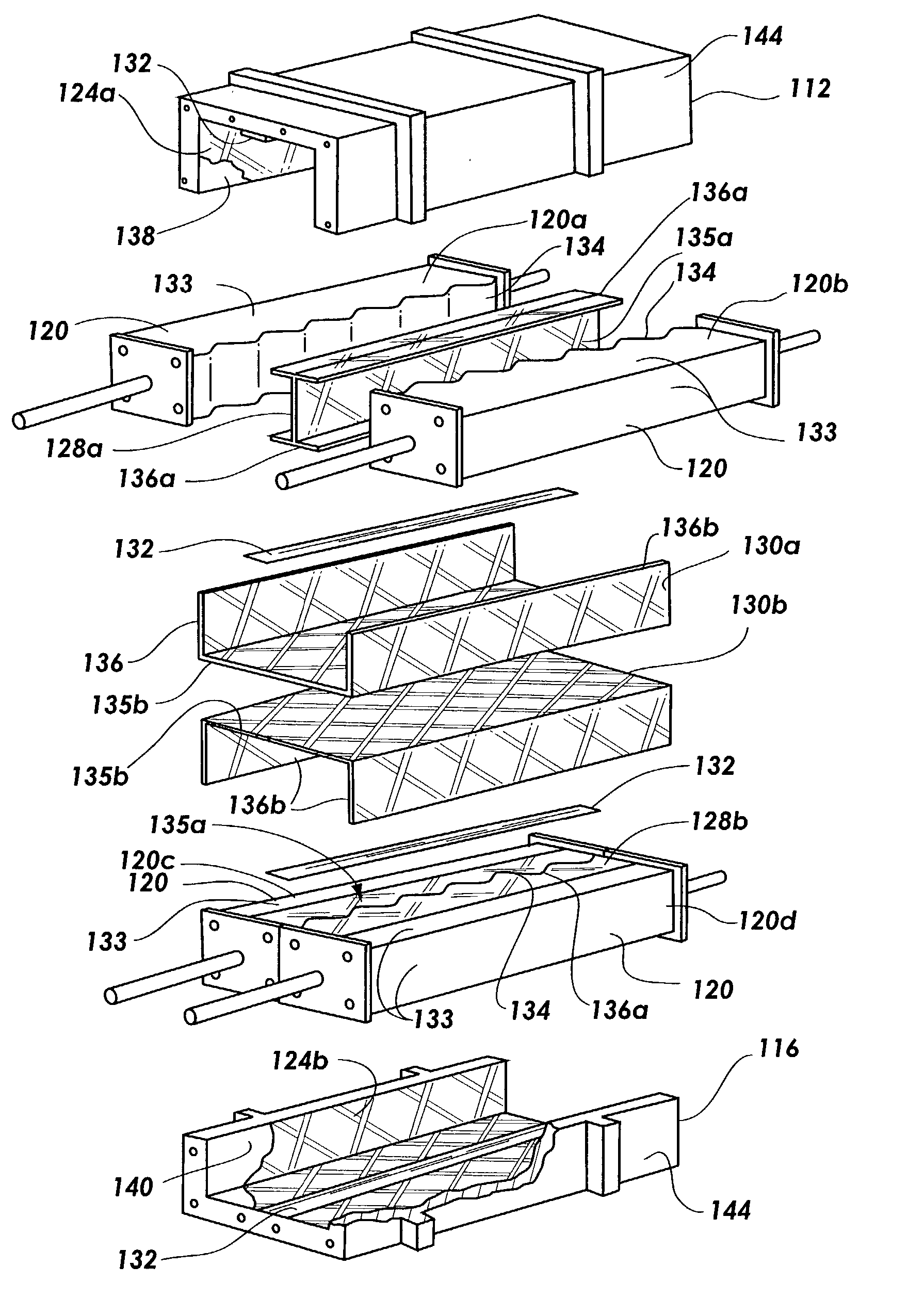
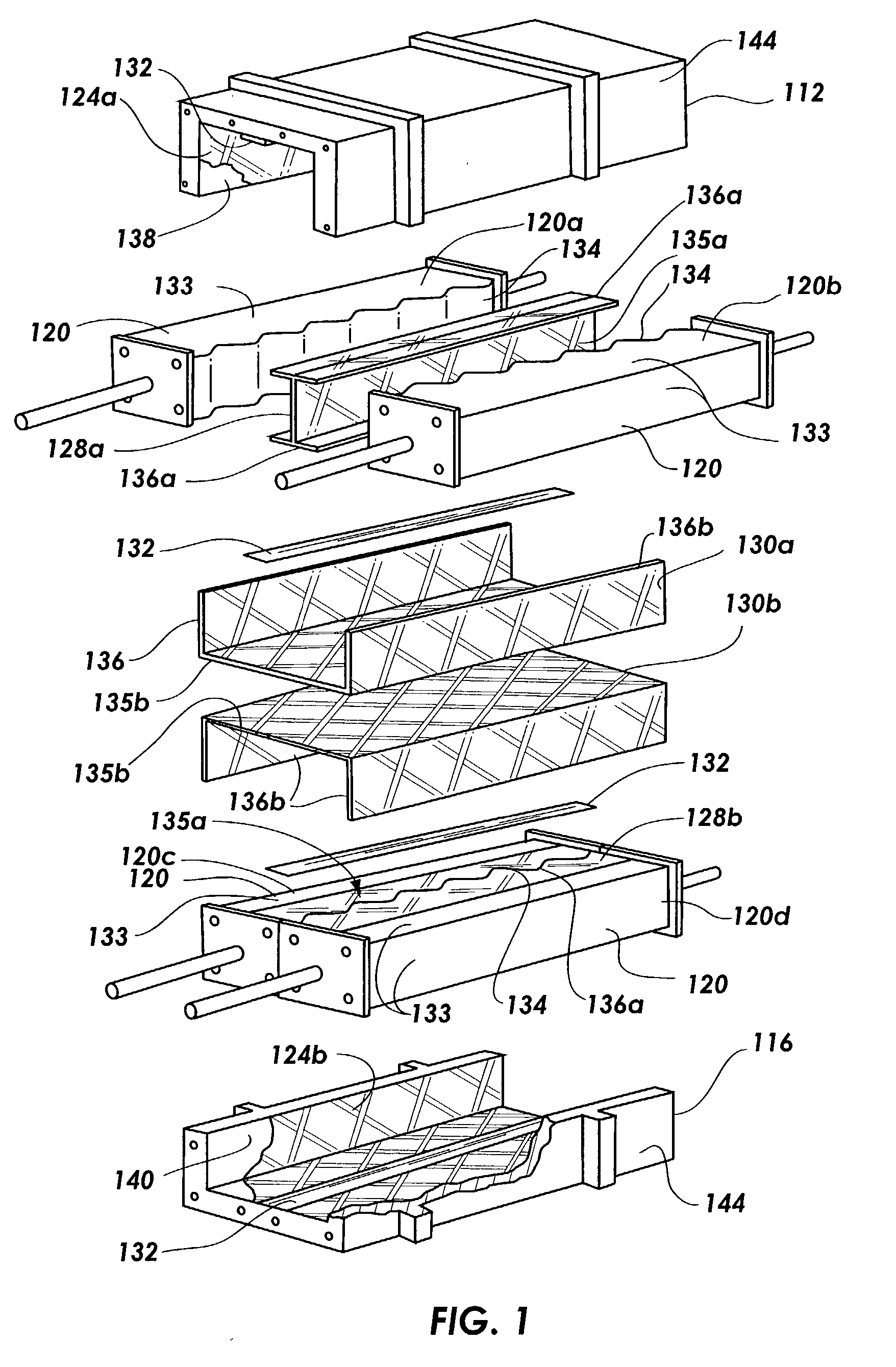
[0022] FIG. 1 is an exploded assembly view of a composite structure being assembled according to the disclosed process.

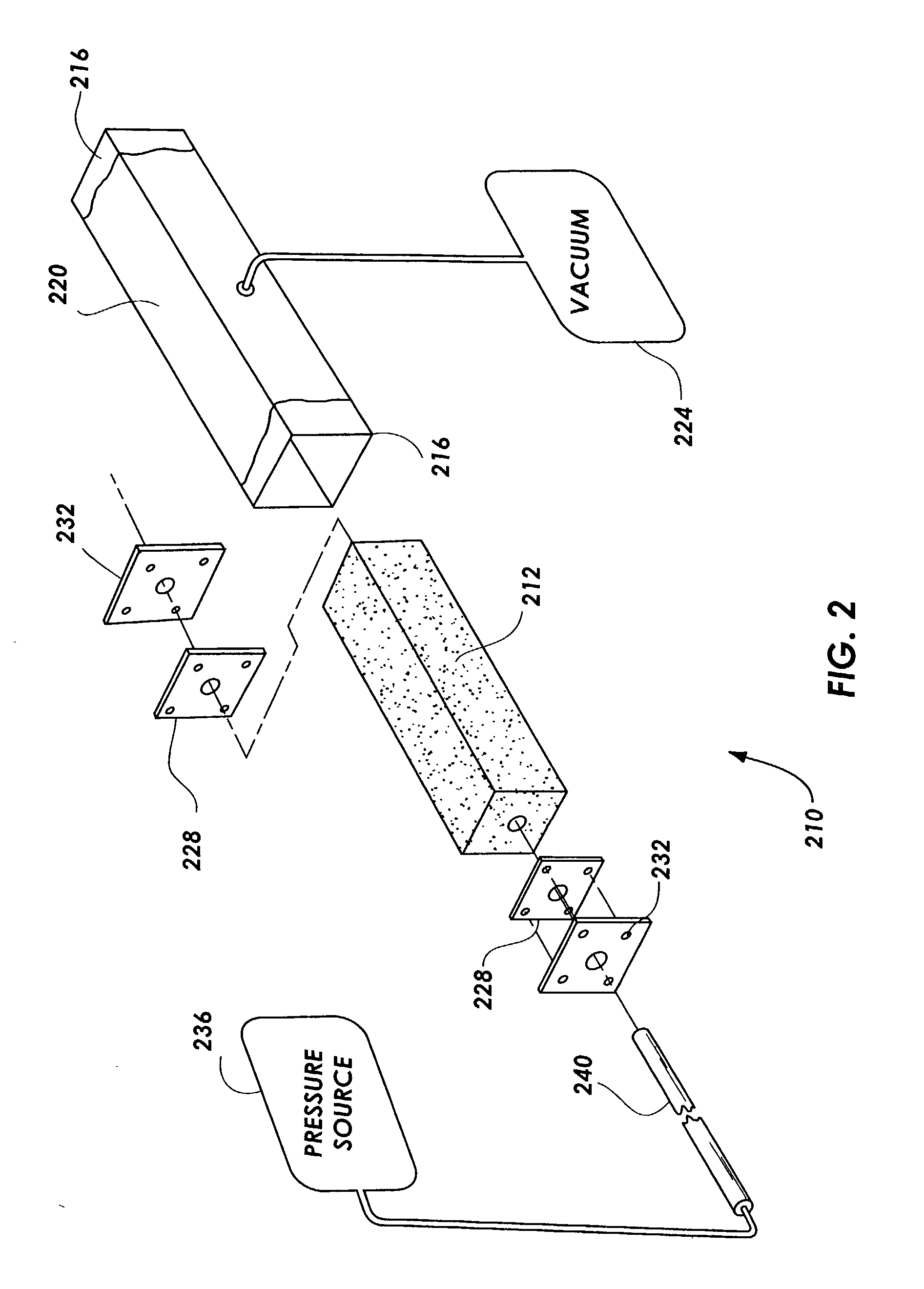
[0023] FIG. 2 is an exploded assembly view of a pressurizable form.

[0024] FIG. 3 is an exploded assembly view of an assembly process for defining an interior surface of a composite structure.

[0025] FIG. 4 is an exploded assembly view of a process for adhering a composite material to a shaping surface.

[0026] FIG. 5 is a cross-sectional view of a single piece co-cured fuselage.

[0027] FIG. 6 is an exploded assembly view of the component employed in forming a single piece co-cured fuselage.

[0028] FIG. 7 is a perspective v...


PUM

PropertyMeasurementUnit
pressureaaaaaaaaaa
pressureaaaaaaaaaa
pressuresaaaaaaaaaa

Abstract

A method for manufacturing a composite structure is disclosed herein. The process uses a frame and selectively pressurizable forms. The forms define the interior members of the composite structure and frames define the exterior surface of the composite structure. Composite material is wrapped around the forms and the forms and composite material are placed in the frame. Selective forms are then pressurized and the composite material is co-cured together. A single piece co-cured fuselage incorporating a plurality of stiffeners is also disclosed in the application. The stiffeners are co-cured to the fuselage and may be in various patterns. The patterns may include an iso-grid pattern, and ortho-grid pattern, and a hoop-grid pattern.

Description

[0001] 1. Field of the Invention[0002] The present invention relates to forming advanced composite materials. More particularly, the present invention relates to a process for creating a single piece co-cured composite structure.[0003] 2. Technical Background[0004] Advanced composite materials have presented a promising alternative to metals, plastics, and fiberglass. Advanced composite materials have the advantage of being very lightweight and have a high strength. Particularly, carbon-epoxy composite material are among the most promising of the advanced composite materials. Composite materials may also be formed into any number of different shapes, depending upon the application. Because of these advantages, composite materials are being employed in many different fields, such as aeronautics.[0005] However, composite materials also have some disadvantages. Composite materials can be several times more expensive than metals or fiberglass. Despite the desirable strength and weight c...

Claims


Application Information

Patent Timeline
Patent Type & Authority Applications(United States)
IPC IPC(8): B29C43/36B21DB29C43/10B29C43/18B29C53/50B29C65/02B29C70/34B29C70/44B29D99/00B29K105/06B29L31/30B64C1/00
CPCB29C70/342B29C70/446Y02T50/433B29L2031/3085Y10S264/904B29L2031/3082B29C70/549Y02T50/40
Inventor SIMPSON, CRAIG B.ALLMAN, MIKE G.TUTTLE, STEVEN T.ASHTON, LARRY J.
Owner SPECTRUM AERONAUTICAL
Why Eureka
Try Eureka