
Fuel injection valve

a fuel injection valve and valve body technology, applied in the direction of fuel injection apparatus, fuel feed system, spraying apparatus, etc., can solve the problems of increased fuel consumption, fixed swirl angle, and inability to adapt to different operating conditions,

Inactive Publication Date: 2004-04-22
ROBERT BOSCH GMBH
View PDF3 Cites 0 Cited by
  • Summary
  • Abstract
  • Description
  • Claims
  • Application Information

AI Technical Summary

Benefits of technology

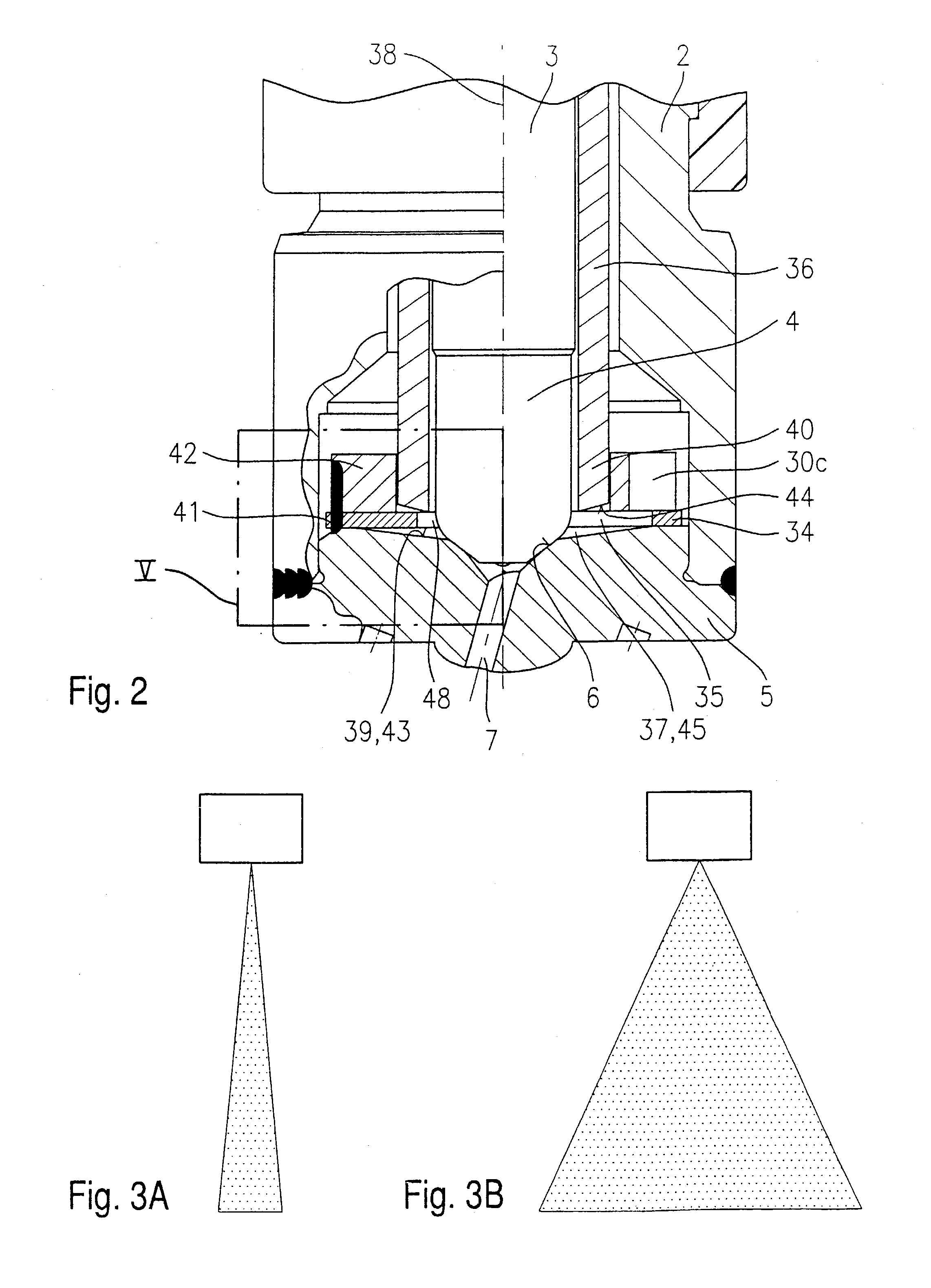
[0004] In contrast, the advantage of the fuel injector according to the present invention having the characterizing features of the main claim is that the swirl is adjustable as a function of the operating state of the internal combustion engine, making it possible to produce a jet pattern adapted to the operating state of the internal combustion engine. This makes it possible to optimize both the mixture formation and the combustion process.[0005] A particular advantage is the simple design of the swirl-producing components, which in contrast to conventional swirl formation, are only augmented by a plunger element, which is simple to manufacture and which is slidable onto the valve needle. The plunger element may be activated by a suitable control unit, for example by piezoelectric, electromagnetic or hydraulic means.[0006] It is also an advantage that the swirl disk of the conventional swirl formation may be taken over without modification.[0007] The measures cited in the dependent claims make advantageous refinements on and improvements of the fuel injector specified in the main claim possible.[0008] In addition, the funnel-shaped, recessed form of the valve-seat member, which makes it possible to deform the swirl disk elastically and accordingly adjust the swirl, is simple to manufacture.[0009] Advantageously, the downstream end of the plunger element has a radial bevel, whose inclination corresponds to that of the funnel-shaped valve-seat member, as a result of which the swirl disk is uniformly deformed and non-homogeneities are prevented.[0010] Also of advantage is the possibility to switch the plunger element into the position appropriate to the present operating state of the fuel injector independently of the lift of the valve needle.

Problems solved by technology

A disadvantage of the fuel injectors known from the publication cited above is in particular the fixedly set swirl angle which cannot be adapted to the different operating states of an internal combustion engine such as partial load and full load operation.
As a result, it is also not possible to adapt the cone apex angle .alpha. of the injected mixture cloud to the various operating states, which results in non-homogeneities during combustion, increased fuel consumption, as well as increased exhaust gas emission.

Method used


Image

  • Fuel injection valve
  • Fuel injection valve
  • Fuel injection valve

Examples


Embodiment Construction

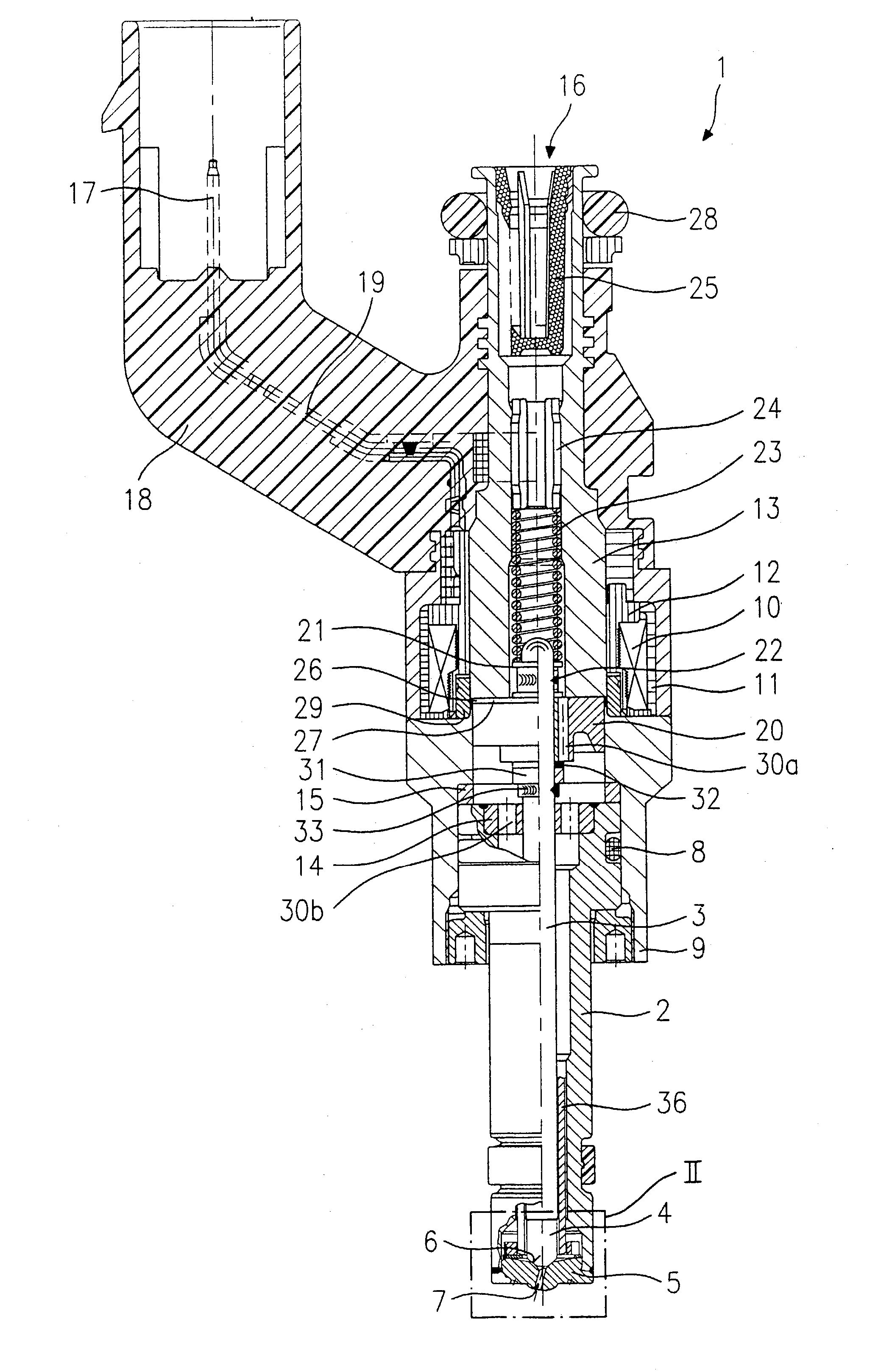
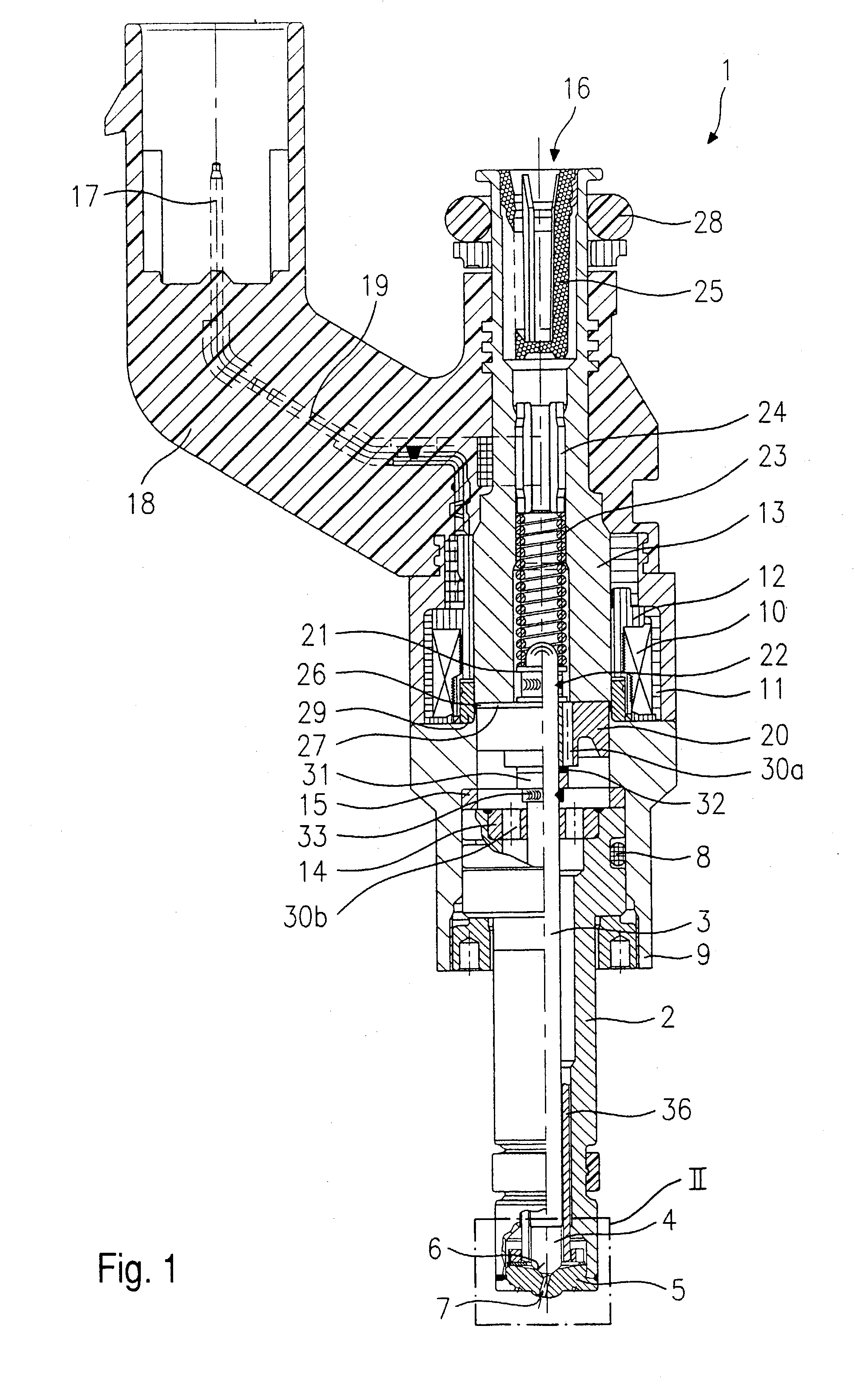
[0017] Before an exemplary embodiment of a fuel injector 1 according to the present invention is described in greater detail based on FIGS. 2 through 5, the essential components of fuel injector 1 according to the present invention will be explained briefly in general terms based on FIG. 1.

[0018] Fuel injector 1 is designed in the form of a fuel injector for fuel injection systems of mixture-compressing, spark-ignited internal combustion engines. Fuel injector 1 is suitable in particular for the direct injection of fuel into a combustion chamber (not shown) of an internal combustion engine.

[0019] Fuel injector 1 includes a nozzle body 2 in which a valve needle 3 is situated. Valve needle 3 is mechanically linked with a valve-closure member 4, which cooperates with a valve seat surface 6 situated on a valve-seat member 5 to form a sealing seat. In the exemplary embodiment, fuel injector 1 is an inwardly opening fuel injector 1 having at least one spray-discharge orifice 7. Nozzle bod...


PUM


Abstract

A fuel injector (1), in particular for fuel injection systems in internal combustion engines, including an actuator (27), a valve needle (3) operable by the actuator (27) for operating a valve-closure member (4), which, together with a valve-seat surface (6) forms a sealing seat and a swirl device (34) having at least one swirl channel (35), through which fuel flows with a tangential component relative to a longitudinal axis (38) of the fuel injector (1). The axial position of a plunger element (36) determines a cross-section of at least one bypass channel (37) that bypasses the at least one swirl channel (35) without a tangential component.

Description

BACKGROUND INFORMATION[0001] The present invention is directed to a fuel injector according to the definition of the species in the main claim.[0002] A fuel injector for the direct injection of fuel into the combustion chamber of a mixture-compressing, spark-ignited internal combustion engine, the fuel injector including a guide and seat area formed by three disk-shaped elements at the downstream end of the fuel injector is known from German Patent Application 197 36 682 A1. A swirl element is embedded between a guide element and a valve seat element. The guide element is used to guide an axially movable valve needle that protrudes through the guide element while a valve closing section of the valve needle cooperates with a valve seat surface of the valve seat element. The swirl element has an inner opening area with multiple swirl channels that are not connected to the outer circumference of the swirl element. The entire opening area extends completely across the axial thickness of...

Claims


Application Information

Patent Timeline
IPC IPC(8): F02M51/06F02M51/08F02M61/16F02M61/18
CPCF02M51/0671F02M61/1806F02M61/18F02M61/162
Inventor RIEGER, FRANZLUDWIG, THOMASSCHLEMBACH, HANSHAAG, GOTTLOBBRENNER, ULRICHHUEBEL, MICHAELSTEIN, JUERGENSIEBER, UDO
Owner ROBERT BOSCH GMBH
Learn More