Masonry anchoring system

a technology of masonry anchoring and jointing, which is applied in the direction of walls, building components, pillars, etc., can solve the problems of jointing having a detrimental effect on the structural stability of the wail structur

Inactive Publication Date: 2004-05-06
MASONRY REINFORCING OF AMERICA
View PDF10 Cites 48 Cited by
  • Summary
  • Abstract
  • Description
  • Claims
  • Application Information

AI Technical Summary

Problems solved by technology

The relatively limited area available for mortar within the mortar joint has a detrimental effect on the structural stability of the wail structure.

Method used


Image

  • Masonry anchoring system
  • Masonry anchoring system
  • Masonry anchoring system

Examples


Embodiment Construction
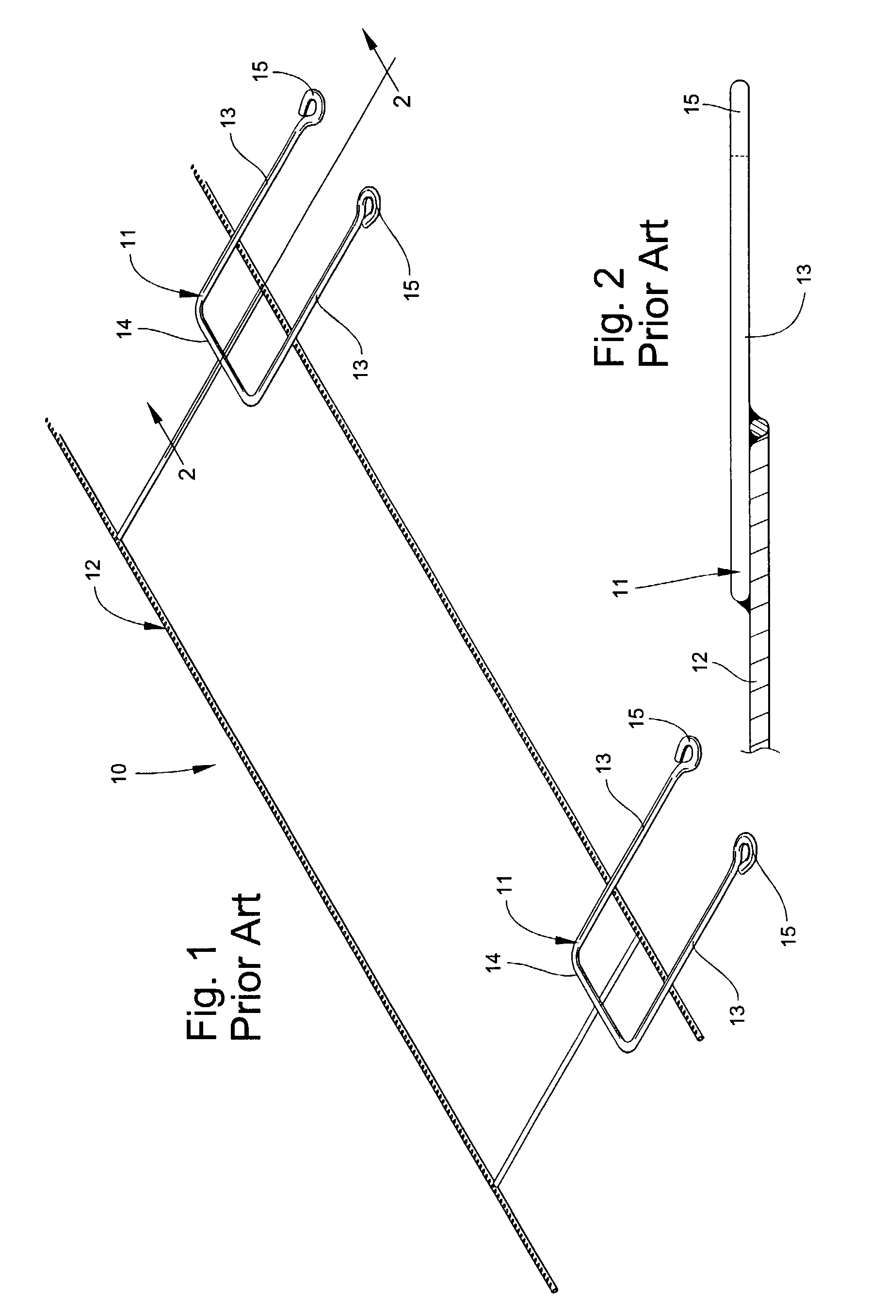
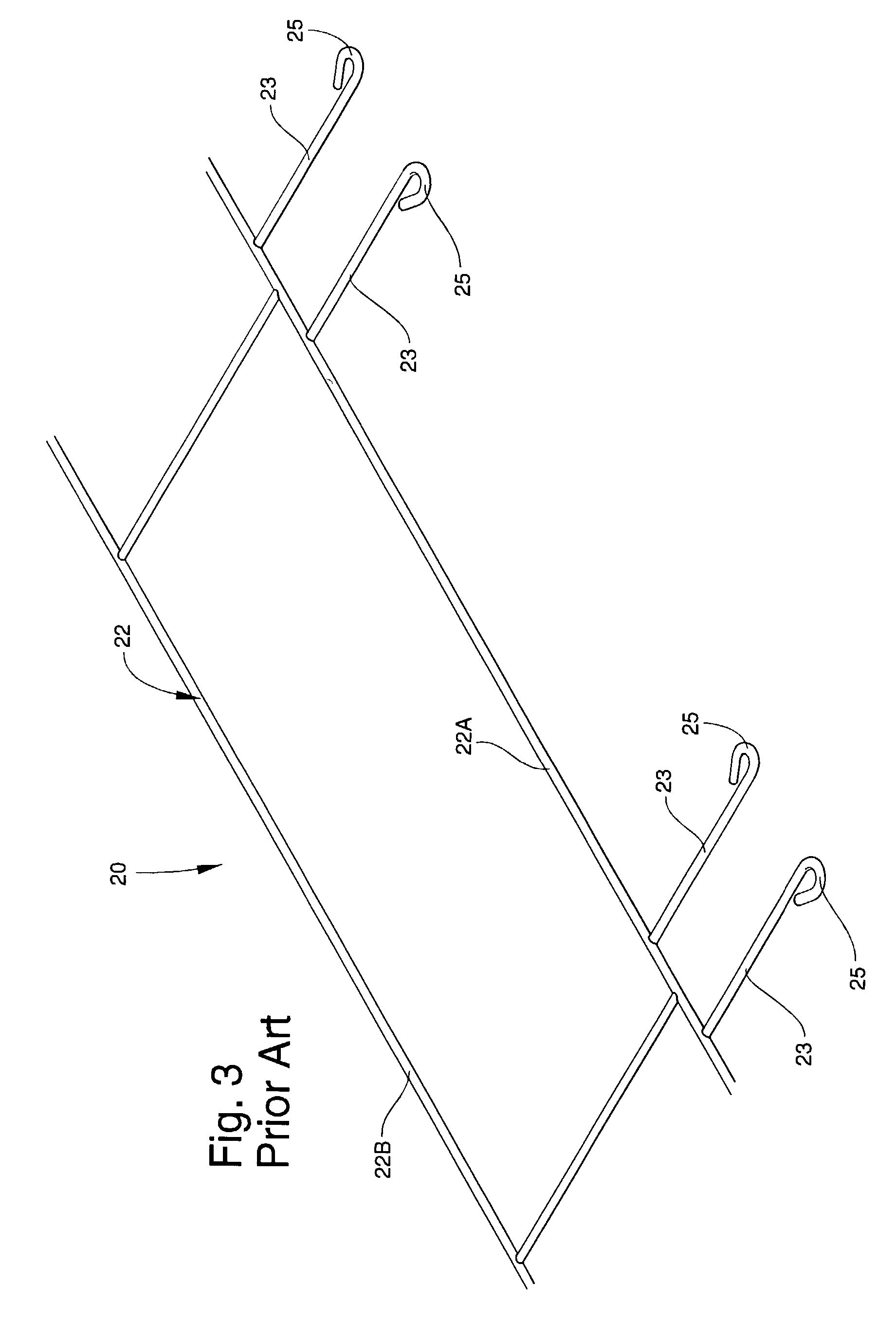
[0030] Prior Art

[0031] Referring now specifically to the drawings, a prior art masonry anchor is illustrated in FIG. 1, and shown generally at reference numeral 10. The prior art masonry anchor comprises U-shaped wire bracket 11 affixed on a ladder-type support frame 12. The U-shaped bracket 11 has a pair of parallel elongate arms 13 connected by a cross wire 14 extending transversely from the support frame 12. Eyes 15 are formed at the ends of the elongate arms 13, and shaped to receive a complimentary connecting member, such as a wall tie.

[0032] As shown in FIG. 2, the U-shaped bracket 11 is welded to one surface of the support frame 12, and occupies a different horizontal plane than the support frame 12. This increases the overall thickness of the anchor 10, resulting in less space available for filling mortar. The support frame 12 is typically comprised of a metal wire having a thickness of 0.148 inch, and the bracket 11 generally has a thickness of 0.187 inch, yielding a total ...


PUM


Abstract

An masonry anchor is disclosed for anchoring two spaced apart masonry walls together to form a single wall structure. The masonry anchor includes a ladder or truss type support frame for positioning on top of a mortar joint in one wall, and a bracket having a pair of elongate arms connected by a cross-member affixed to the support frame. The cross-member is angled for providing two spaced apart points on the cross-member for contacting the support frame and affixing the cross-member thereto. The elongate arms extend transversely from the support frame and are sized to extend into the space between the two walls. Each of the arms have an eye portion formed at the end opposite the cross-member to receive a connecting member connected to the second wall. The support frame and the bracket reside in the same horizontal plane.

Description

TECHNICAL FIELD AND BACKGROUND OF THE INVENTION[0001] The invention relates to a masonry anchor for use in connecting two spaced apart masonry walls to form a single unified wall structure. The masonry anchor of the present invention can be easily and efficiently produced, and results in improved structural stability in the wall structure.[0002] It is common in masonry construction for wall structures to comprise an inner wall, typically of concrete block construction to provide structural stability, and a spaced-apart outer veneer wall, often made of brick, principally for aesthetic purposes. Masonry anchors have long been used for anchoring the two walls together to help form a single unified wall structure. Prior art masonry anchors are generally made of metal wire and typically comprised a ladder or truss-type support frame that is positioned on a mortar joint of the inner wall coplanar with a mortar joint in the outer wall. A plurality of U-shaped brackets extend outwardly from...

Claims


Application Information

Patent Timeline
Patent Type & Authority Applications(United States)
IPC IPC(8): E04B1/41E04B2/02
CPCE04B2/02E04B1/4185
Inventor JOHNSON, RALPH O. III
Owner MASONRY REINFORCING OF AMERICA
Why Eureka
Try Eureka