Shock absorber for vehicles

a technology for shock absorbers and vehicles, applied in the field of vehicle shock absorbers, can solve the problems of not being able to say that the weight is identical, not being able to be sharply enlarged, and not being able to form the hollow of the housing in an enclosed manner

Inactive Publication Date: 2004-05-06
SUMITOMO RIKO CO LTD
View PDF8 Cites 28 Cited by
  • Summary
  • Abstract
  • Description
  • Claims
  • Application Information

AI Technical Summary

Problems solved by technology

However, when reinforcement plates are added or the thickness of metallic plates is increased, it is inevitable to result in sharply enlarging the weight.
Although the shock resistance is an ability of materials to endure shocks without breaking or being destroyed, it is not necessarily possible to say that it is identical with the shock-energy absorbing characteristic.
The hollow of the housing cannot necessarily be formed in an enclosed manner.
When the tensile breaking elongation is less than 200%, it is

Method used


Image

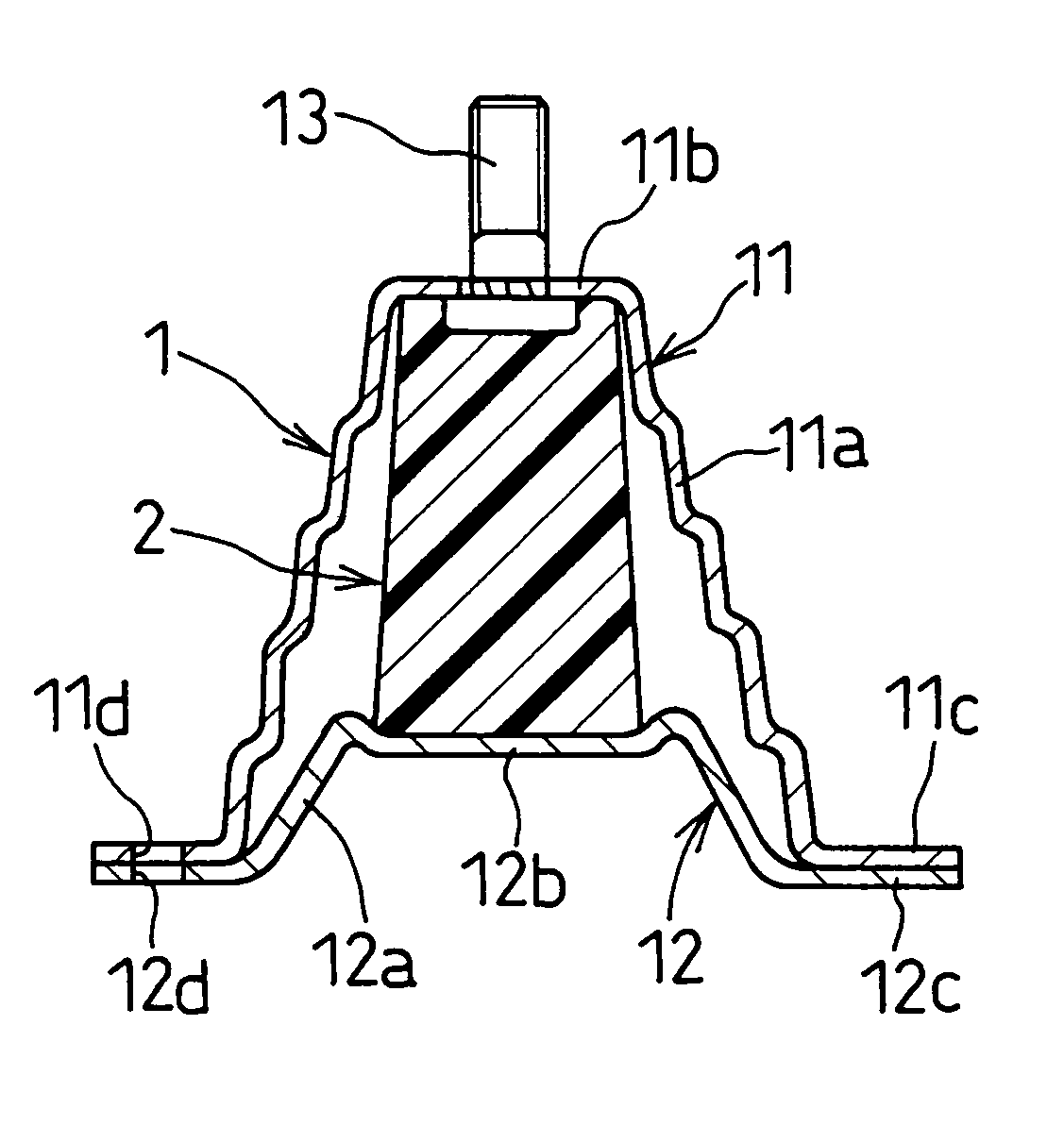
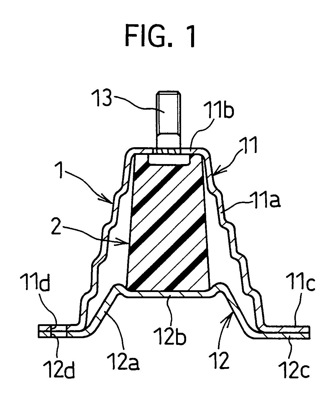
  • Shock absorber for vehicles
  • Shock absorber for vehicles
  • Shock absorber for vehicles

Examples


example no.2

EXAMPLE NO. 2

[0060] FIG. 4 is a front view partly in cross-section for illustrating how a vehicle shock absorber according to Example No. 2 of the present invention is installed to an impact beam. FIG. 5 is a cross-sectional view of the present vehicle shock absorber taken in the direction perpendicular to the axial direction, e.g., in the direction of the arrows "5"-"5" of FIG. 4.

[0061] The present vehicle shock absorber according to Example No. 2 is equipped with vehicle doors, and is then installed to impact beams which absorb shock energies upon colliding. As illustrated in FIGS. 4 and 5, the present vehicle shock absorber comprises a cylinder-shaped housing 3, and a cylinder-shaped shock-energy absorbing member 4. The housing 3 is fastened outside an impact beam coaxially. The shock-absorbing member 4 is disposed in a hollow formed between the housing 3 and the impact beam 5, and is composed of a super plastic polymer material. Note that the impact beam 5 is herein formed by cu...

example no.3

EXAMPLE NO. 3

[0069] FIG. 7 is a cross-sectional view for illustrating a vehicle shock absorber according to Example No. 3 of the present invention.

[0070] The present shock absorber according to Example No. 3 is installed to a side sill which is disposed on a body floor of vehicles to extend in the width-wise direction of vehicles. The shock absorber utilizes a side sill, a bone structural member of vehicles, as the housing, one of the component parts. As illustrated in FIG. 7, the shock absorber comprises a housing 6, and a shock-energy absorbing member 7. The housing 6 comprises an outer member 61 and an inner member 62 which make a side sill, and has a hollow therein. The shock-absorbing member 6 is disposed in the hollow of the housing 6, and is composed of a super plastic polymer material.

[0071] Specifically, the housing 6 comprises the outer member 61, and inner member 62 which are composed of a continuously-long thin ferrous metallic plate, respectively. At the middle in the w...


PUM


Abstract

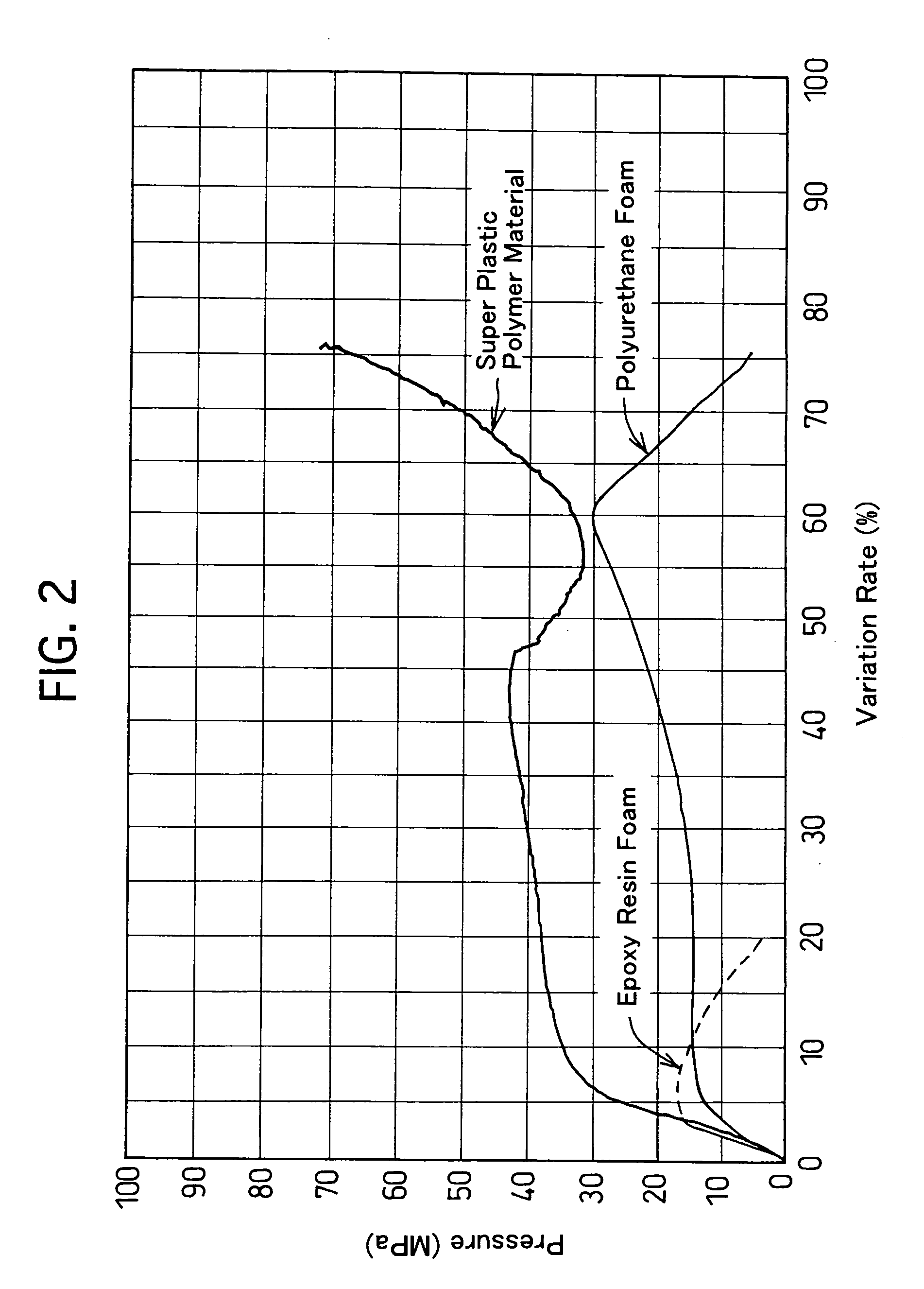
A vehicle shock absorber includes a housing, and a shock-absorbing member. The housing has at least one hollow formed therein, is formed of a rigid material, and is fixed to a bone structural member of vehicles. The shock-energy absorbing member is disposed in the hollow of the housing at least, and is formed of a super plastic polymer material. The super plastic polymer material exhibits a tensile breaking elongation of 200% or more, a yield strength of 20 MPa or more with respect to a predetermined strain, and a tensile elastic modulus of 400 MPa or more.

Description

[0001] 1. Field of the Invention[0002] The present invention relates to a vehicle shock absorber which can be used suitably in bone structural members, such as vehicle frames, bodies and door impact beams, for example.[0003] 2. Description of the Related Art[0004] A variety of shock absorbers or suspensions have been employed conventionally in vehicle frames or panel boards in order to protect human bodies by absorbing shocks upon colliding. For example, bumper beams or crush boxes are installed to the front and rear of vehicle frames in order to absorb shock energies when vehicles collide. The shock absorbers are usually formed of metal such as iron and aluminum alloys, and are hollow-structured so as to have a hollow therein in order to avoid the weight enlargement.[0005] Moreover, the following techniques have been employed in order to upgrade the shock-energy absorbing ability of the shock absorbers: adding reinforcement plates, and increasing the thickness of metallic plates ma...

Claims


Application Information

Patent Timeline
IPC IPC(8): B60J5/04B60R19/04B60R19/18B60R19/22B60R19/24B60R19/34B60R19/42B60R21/02B62D21/15B62D24/02F16F7/00F16F7/12F16F9/30F16F15/08
CPCB60J5/0444B60J5/0447B60R19/34B60R19/42F16F9/30B62D21/15B62D24/02F16F7/12B60R2019/1806
Inventor KATO, RENTAROAOI, TAKAHIRO
Owner SUMITOMO RIKO CO LTD
Why Eureka
Try Eureka