Reflector and antenna system containing reflectors

a technology of reflectors and reflectors, applied in the field of reflector antennas, can solve the problems of high transmission loss, inability to meet in-space requirements in rigidity and thermal stability of antennas, and antenna types that cannot be used under special conditions

Inactive Publication Date: 2004-05-06
SAAB ERICSON SPACE
View PDF5 Cites 5 Cited by
  • Summary
  • Abstract
  • Description
  • Claims
  • Application Information

AI Technical Summary

Problems solved by technology

However, this type of antenna cannot be used under the special conditions imposed by in-space applications, since far too many rods would be needed to achieve sufficient reflection in the relevant frequency band.
This antenna is also unable to meet in-space requirements in terms of rigidity and thermal stability.
One problem with this antenna is that the design of the reflector el...

Method used


Image

  • Reflector and antenna system containing reflectors
  • Reflector and antenna system containing reflectors
  • Reflector and antenna system containing reflectors

Examples


Embodiment Construction

[0008] One object of the present invention is to provide a reflector antenna that is an improvement over the state of the art, which means that the reflectors can function in higher frequency bands than previous design solutions, while the design of the reflector antenna is at the same time simplified.

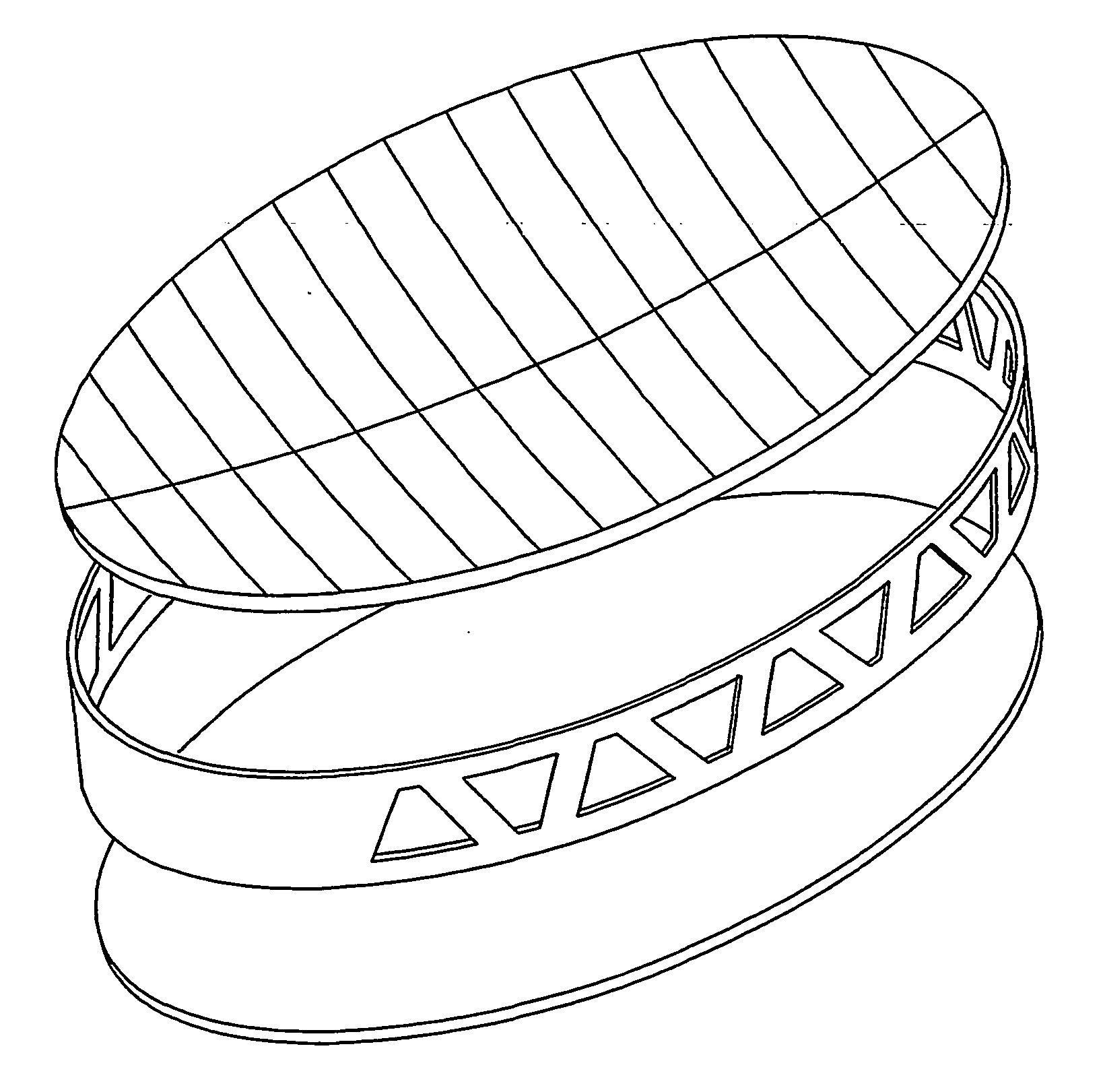
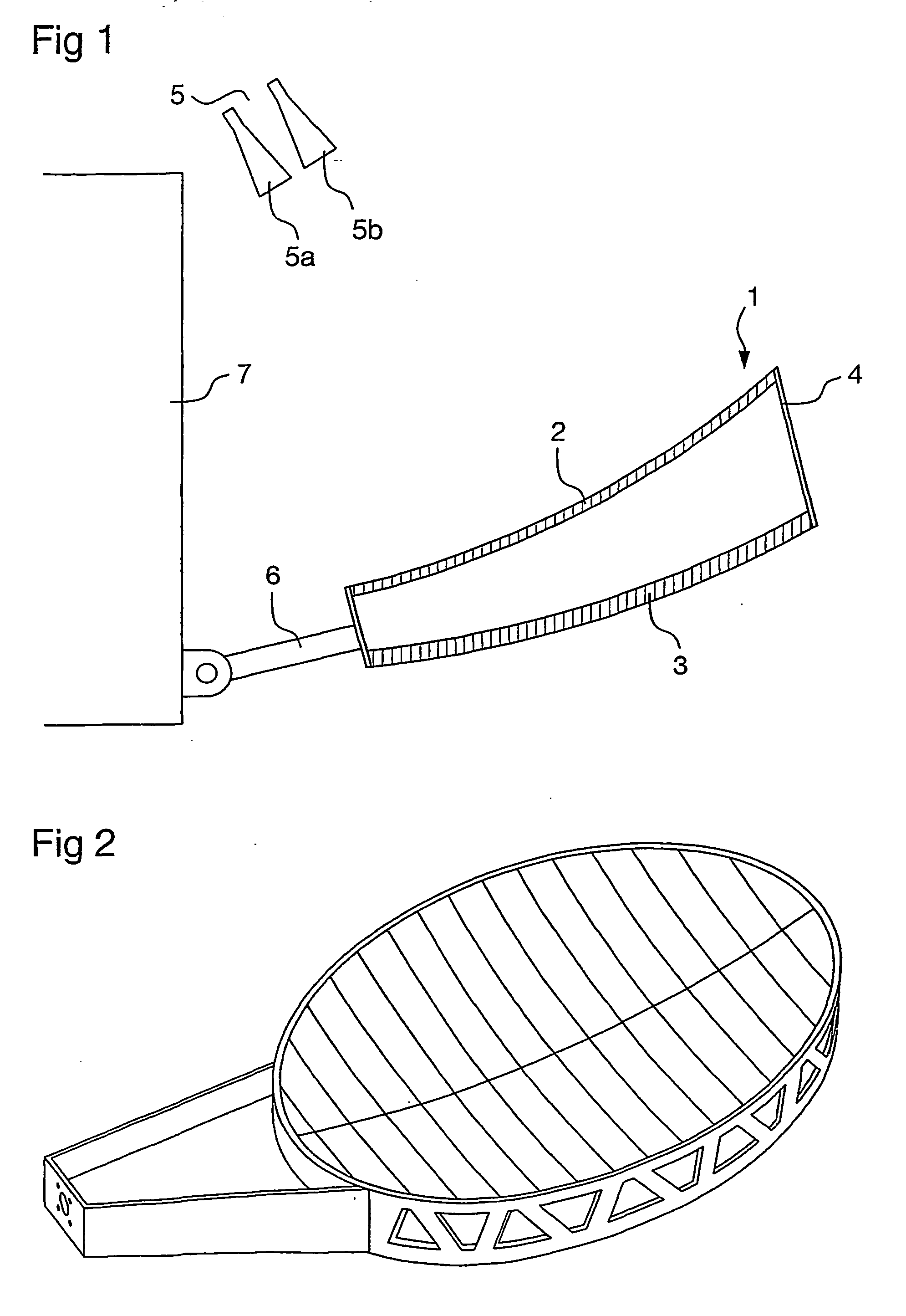
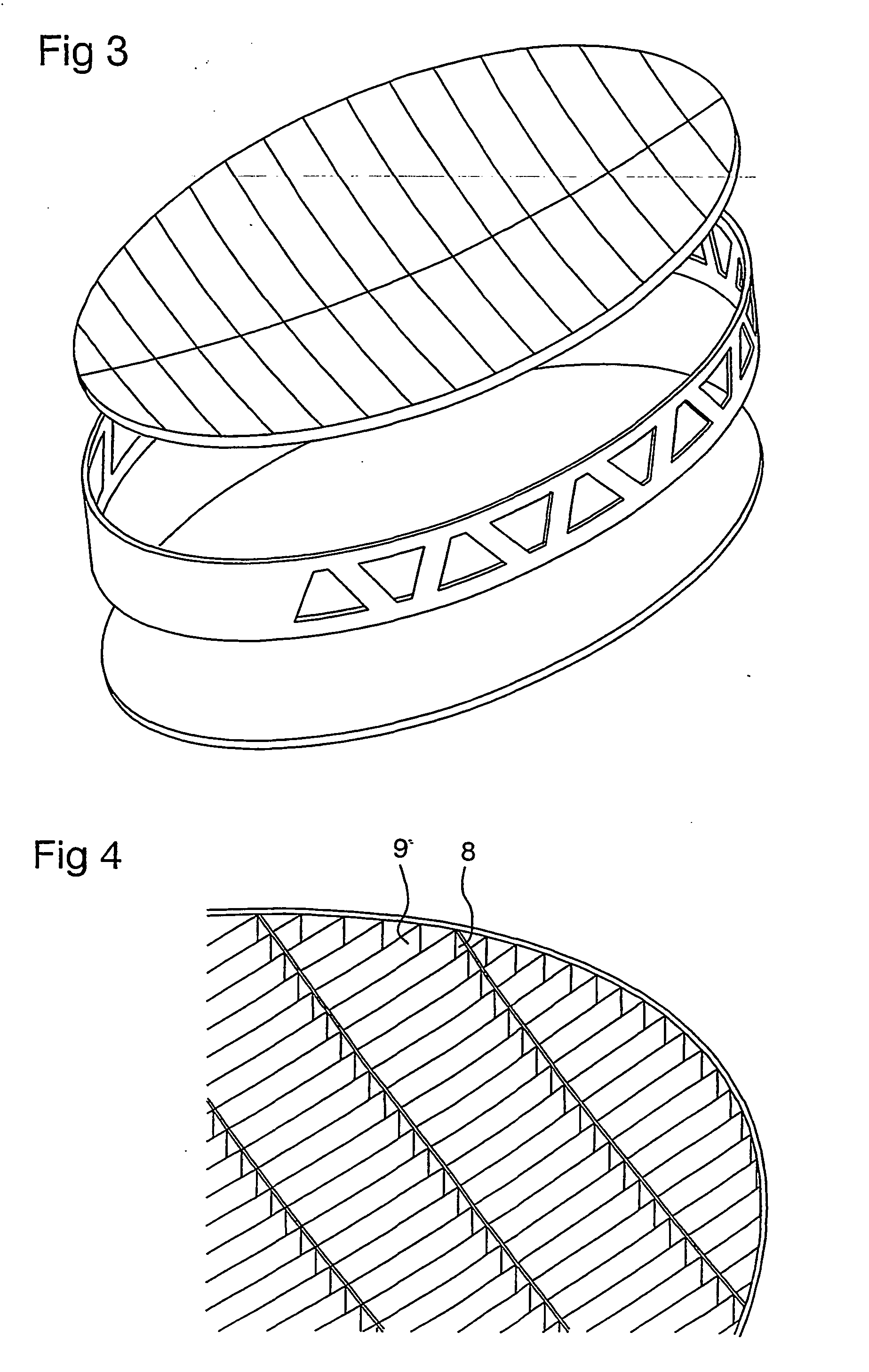
[0009] This has been accomplished by means of a reflector according to claim 1, in which a first reflector element comprises a lattice structure of electrically conductive plates disposed at a uniform distance apart from one another, wherein the distance between the plates and the depth of said plates is adapted for the reflection of polarization parallel with the plates. The extent of each respective plate toward the second reflector element is chosen so that the transmission losses in the first reflector element are minimized.

[0010] In an alternative embodiment of the invention the plates in the lattice structure are arranged in such a way that each respective plate in the lattice st...


PUM


Abstract

The invention concerns a reflector and a satellite antenna system comprising such a reflector. In the satellite antenna system, microwave radiation from one or more feed horns (5) is emitted at the reflector (1), which comprises first and second reflector elements (2, 3). Upon reflection of the radiation from the reflector elements (2, 3), a distinct beam shape for the reflected microwave energy is generated. The reflector elements (2, 3) are disposed at a fixed distance from one another so that radiation that passes the first reflector element (2) strikes the second element. The first reflector element (2) comprises a lattice structure aimed toward feed horn, which lattice structure consists of plates (8) of electrically conductive material, wherein the distance between the plates and the depth of said plates are adapted for reflection of polarization parallel to the plates. The invention is characterized in that the extent of each respective plate toward the second reflector element is chosen so that the transmission losses in the first reflector element are minimized.

Description

TECHNICAL AREA[0001] This invention concerns a reflector with first and second reflector elements disposed relative to one another in such a way that radiation that passes the first reflector element strikes the second reflector element, wherein the first reflector element comprises a lattice structure of electrically conductive plates disposed at a uniform distance from one another, wherein the distance between the plates and the depth of said plates are adapted for the reflection of polarization parallel with the plates. The invention also concerns a satellite antenna system in which microwave radiation is emitted from one or more feed horns toward the reflector.BACKGROUND AND PROBLEM OF THE INVENTION[0002] Communication satellites furnish signals to large geographical areas on the ground. Specially adapted antenna designs make it possible to provide signal coverage for a particular reception area or country. An antenna system comprising one or a plurality of feed horns that trans...

Claims


Application Information

Patent Timeline
IPC IPC(8): H01Q3/26H01Q15/22H01Q19/12H01Q19/195H01Q21/28H01Q25/00
CPCH01Q3/2658H01Q15/22H01Q19/12H01Q25/007H01Q21/28H01Q25/001H01Q19/195
Inventor PETERSSON, MIKAELINGVARSON, PER
Owner SAAB ERICSON SPACE
Why Eureka
Try Eureka