
Heat nozzle for welding floor seams

a technology of heating nozzle and floor seam, which is applied in the direction of furniture, paper hanging, lighting and heating apparatus, etc., can solve the problems of unsightly appearance, significant deterioration of the floor, and inadequate adhesive bond between the underside of the flooring sheet and the subfloor therebeneath

Inactive Publication Date: 2004-05-20
MARTINEZ LEO
View PDF9 Cites 8 Cited by
  • Summary
  • Abstract
  • Description
  • Claims
  • Application Information

AI Technical Summary

Benefits of technology

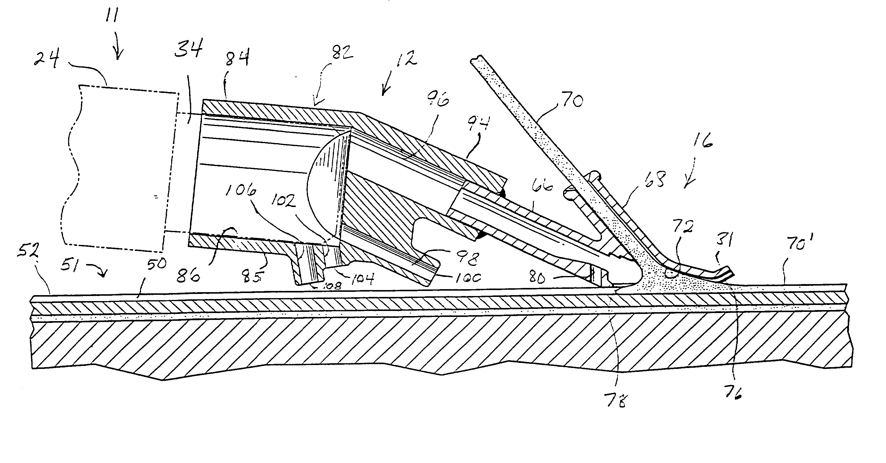
[0020] Even more rapid preheating is achieved by providing second and third heating jets in the heat nozzle of the invention. These second and third heating jets are preferably oriented at an angle of between forty and sixty-six degrees relative to the first heating jet so that they emit jets of hot air that heat the material of the flooring at the seam even in advance of the first preheating jet which directs hot air at the seam just behind the welding tip. As a consequence, the speed at which a flooring seam can be filled with sealant material is greatly increased relative to the speed with which this task can be performed utilizing conventional handheld seam welding guns equipped with "pencil tip" adapters.
[0021] As previously indicated, an experienced flooring installer can operate a conventional, handheld flooring seam welding gun to perform a professional seam sealing job at the rate of about four feet per second. However, utilizing the same welding gun and essentially the same welding tip, but employing a heat nozzle according to the invention in place of a "pencil tip" adapter, the rate of seam sealing can be approximately tripled. That is, utilizing the same heat welding gun and welding nozzle, but with the adapter of the invention, an installer can fill seams at the rate of about twelve feet per minute.

Problems solved by technology

One major problem with laying sheets of flooring in this manner is that the adhesive bond between the underside of the flooring sheets and the subfloor therebeneath is sometimes inadequate.
Quite often areas of the sheets of the linoleum flooring will tend to separate from the subfloor when the adhesive bond between the subfloor and the flooring sheets deteriorates due to age, movement of the subfloor, or improper installation.
This presents both an unsightly appearance and also leads to a significant deterioration of the floor because of the separation that occurs when the edges of adjacent sheets of flooring rise.
When separation between adjacent sheets of flooring occurs in this way, moisture, dirt and debris often find their way into the crack that forms between the flooring sheets, thus leading to further deterioration of the floor.
While automated seam sealing machines of the type described do create firm, durable sealed seams between adjacent sections of sheet flooring, they are quite large, bulky, heavy, and complicated to operate.
Furthermore, they are quite expensive so that their cost is well beyond the resources of the average sheet flooring installer.
While conventional, handheld, portable seam welding guns of the type described can produce high-quality seams, the rate at which the seam can be filled with sealant utilizing a portable, handheld welding gun is rather limited.
In contrast, the expensive, automated seam sealing machines of the type described can be operated to fill seams at the rate of about sixteen feet per minute.
In a conventional device such as this the volume of hot air that may be forced into the hollow heating tip is rather limited.
Consequently, the rate at which the sticks or rods of plastic sealant can be melted and the floor seam heated beneath the melting chamber in the welding tip is limited.
Consequently, there is a constriction in air flow into the hollow welding tip, which limits the rate at which the sealant can be melted and dispensed in molten form to fill a seam between adjacent flooring sheets.

Method used


Image

  • Heat nozzle for welding floor seams
  • Heat nozzle for welding floor seams
  • Heat nozzle for welding floor seams

Examples


Embodiment Construction

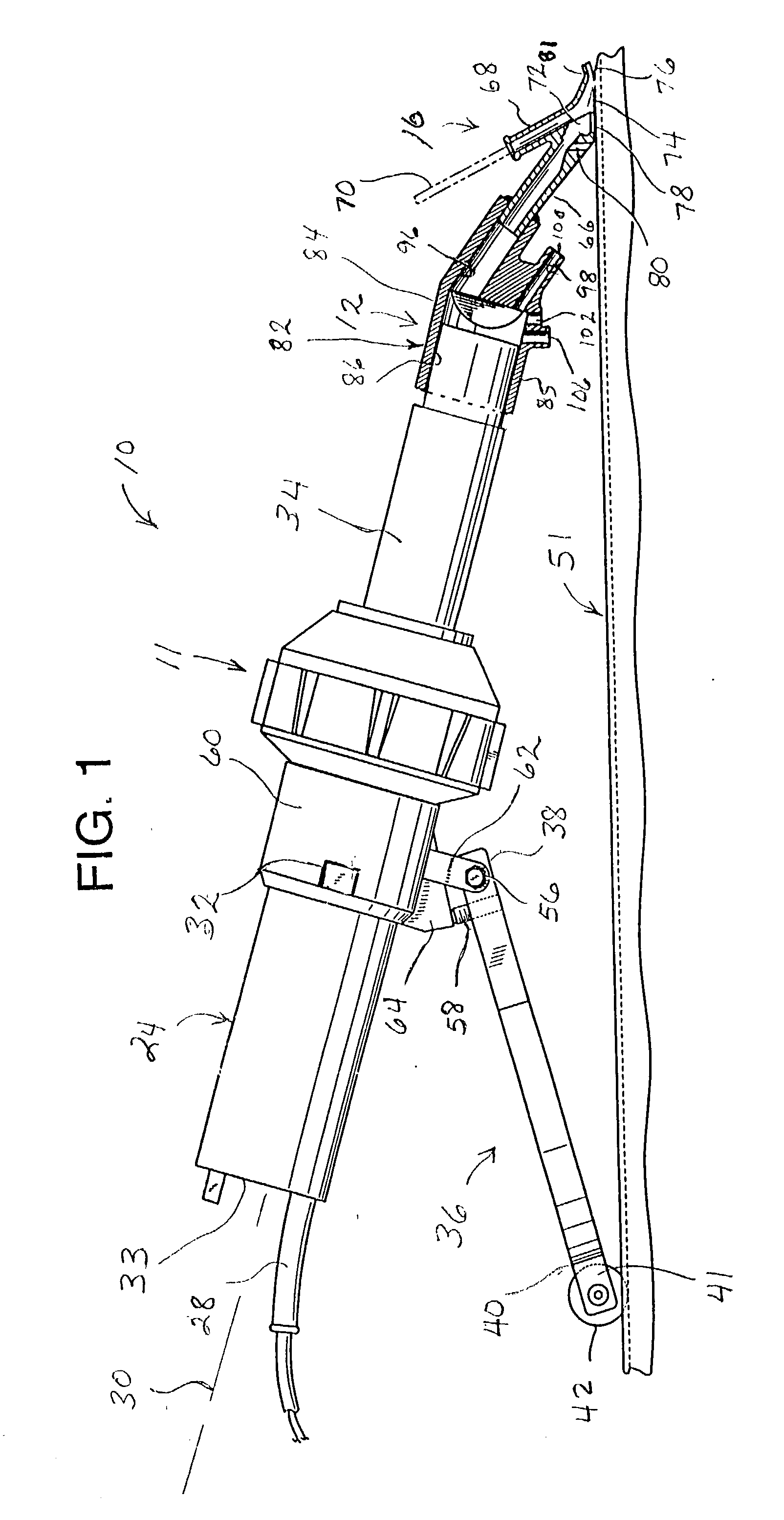
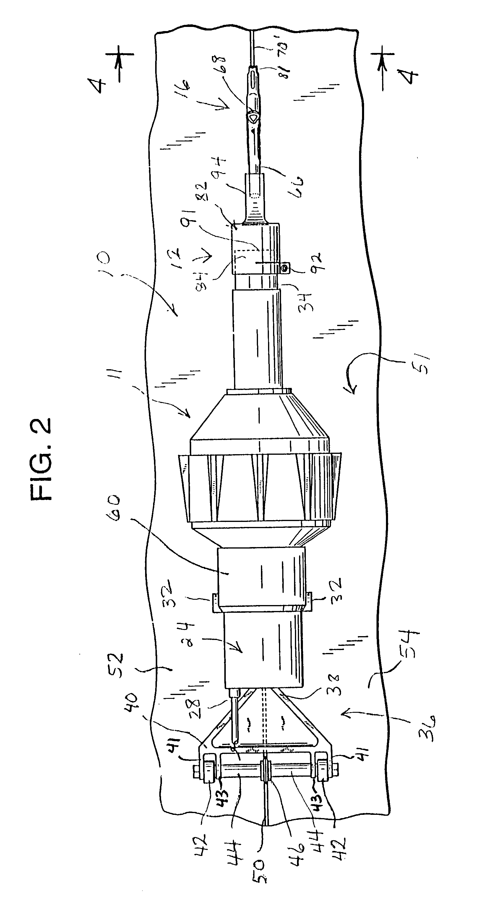
[0034] FIG. 1 depicts a device, indicated generally at 10, for sealing seams between adjoining, abutting sheets of flooring 52 and 54 on a flat floor surface 51. The seamsealing device 10 is comprised of a portable, handheld, seam-sealing welding gun 11 equipped with a heat nozzle 14 constructed according to the invention, and also a hollow heat welding tip 16. The heat welding gun 11 is a conventional, Leister Triac model portable, handheld floor seam welding gun. The generally cylindrical casing 24 of the seam welding gun 11 defines a longitudinal axis indicated at 30. The welding gun 11 is powered by commercially available, alternating current through a power supply cord 28. Near its front end the outer casing 24 of the heat welding gun 11 defines a pair of diametrically opposed, radially outwardly projecting lugs 32 having a rectangular configuration, as illustrated.

[0035] Heat is produced within the casing 24 by an electrical resistance heating element. A blower within the casi...


PUM

PropertyMeasurementUnit
Angleaaaaaaaaaa
Angleaaaaaaaaaa
Angleaaaaaaaaaa

Abstract

A portable, handheld seam welding gun for filling in seams between sheets of linoleum flooring is provided with a unique heat nozzle. The heat nozzle of the invention couples the heating barrel of a conventional floor seam welding gun to a conventional hollow welding tip by receiving the heating air inlet tube of the tip within the confines of a downstream socket formed in the body of the heat nozzle. A larger, upstream socket formed in the body of the heat nozzle fits onto the heating barrel of the handheld, portable welding gun. A plurality of preheating jets are formed on the underside of the body of the heat nozzle to preheat the region of the channel immediately to the rear of the welding tip just before molten sealant flows into that portion of the channel.

Description

[0001] 1. Field of the Invention[0002] The present invention is a heat nozzle designed for use with a portable, handheld seam sealing welding gun for dispensing a molten sealant to join adjacent sheets of flooring.[0003] 2. Description of the Prior Art[0004] In laying flooring that is sold commercially in sheets, such as linoleum flooring, adjacent sheets of flooring are positioned side by side and cut to the desired shape. In the past the flooring sheets have been secured to the floor by adhesive compound. To secure the flooring sheets to the floor, the compound is applied to the floor and the cut sheets of flooring are laid in position, one by one. Once each sheet of flooring is laid, the next adjacent flooring sheet is brought into position and pressed against the floor with the linear edges of adjacent flooring sheets residing in mutual abutment.[0005] One major problem with laying sheets of flooring in this manner is that the adhesive bond between the underside of the flooring ...

Claims


Application Information

Patent Timeline
IPC IPC(8): B29C65/00B29C65/12
CPCB29C65/12B29C66/836B29C66/0242B29C66/1142B29C66/43B29C66/80B29C66/8167B29C66/861B29C66/86535B29K2027/06B29K2711/04B29L2031/732B29C66/024B29C66/435B29C65/125Y10T156/179B29C65/00
Inventor MARTINEZ, LEO
Owner MARTINEZ LEO
Learn More