
Intervertebral disc repair

a technology for intervertebral discs and discs, applied in the field of intervertebral disc repair, can solve the problems of progressive degeneration of the spine, slow healing of annular tissue, and fatigue/failure of instruments, so as to minimize segmental instability, slow healing, and reduce the effect of nerve impingemen

Inactive Publication Date: 2004-05-20
YEUNG JEFFREY E +1
View PDF28 Cites 210 Cited by
  • Summary
  • Abstract
  • Description
  • Claims
  • Application Information

AI Technical Summary

Benefits of technology

[0022] Instability across the motion segment (vertebral body-disc-vertebral body) can occur as the disc degenerates. Segmental instability resembles an out-of-control car riding on one or more flat tires with deflated and unsupported sidewalls. A flattened intervertebral disc causes excessive movement between vertebral bodies, leading to pain in surrounding ligaments and facet joints. Depletion of nucleus pulposus from the percutaneous nuclectomy procedure can accelerate disc flattening or thinning, leading to segmental instability and / or spinal stenosis. Although it might not be grossly detected radiographically, this instability is most apparent during compressional or rotational movements. Under normal conditions, the spinal motion segment and particularly the neuroforamen can smoothly and symmetrically accommodate rotational motions, as well as flexion and extension, without significant alteration of available space. However, as the disc degenerates, the ligaments buckle, the facet joints mal-align and unstable movement appears during routine vertebral motions. With narrowing of the central canal and neuroforamen, unstable vertebral movements produce irritation, inflammation and pain.
[0024] The axial compression force upon the L5-S1 level is between 1500 and 2500 N, bending moment between 15 NM and 25 NM. Due to the curvature of the spine, approximately 20% of the axial compression force is a forward-directed shear force. (Bergmark A., Acta Orthop Scand Suppl:230-238, 1989). As the shear force works on an aging and degenerating disc, the forward sliding process begins. The shear force intensifies as the L5 moves forward and provides more and more leverage. Finally, the ventral (forward) sliding of L5 in relation to S1, called spondylolisthesis, brings a great deal of pain from many possible nerve impingements, including impingement by the transverse process and ligament.

Problems solved by technology

The common problems associated with the techniques are scarring, instrument fatigue / failure and / or progressive degeneration of the spine.
Annular tissue is slow to heal.

Method used


Image

  • Intervertebral disc repair
  • Intervertebral disc repair
  • Intervertebral disc repair

Examples


Embodiment Construction

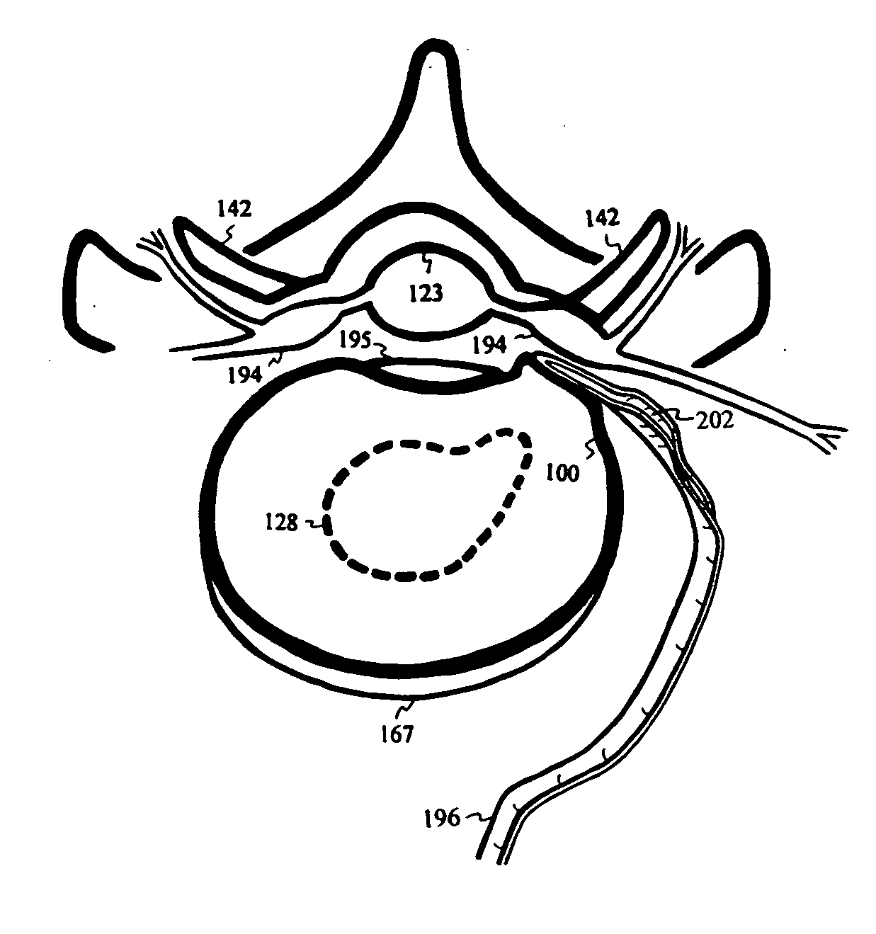
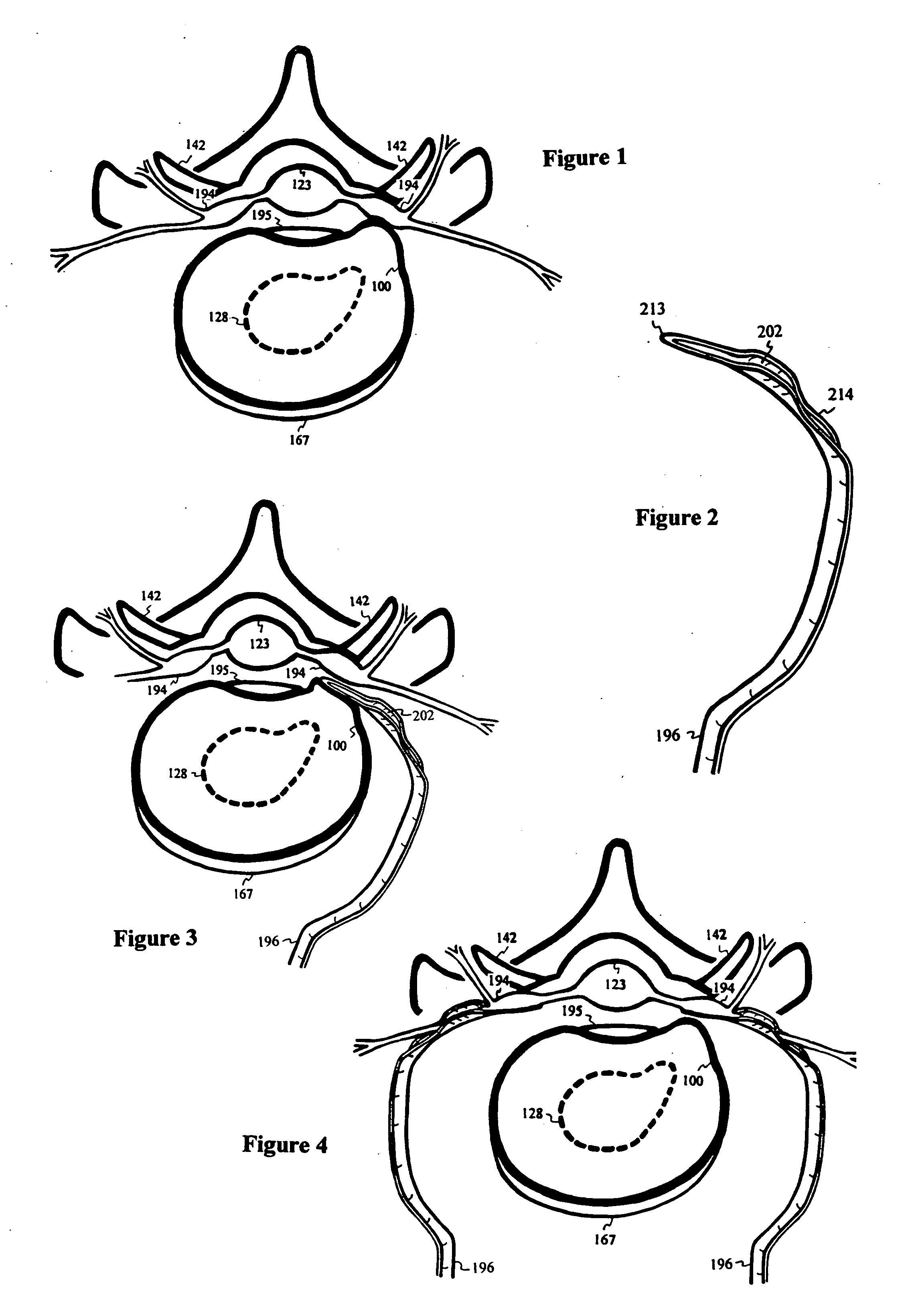
[0124] FIG. 1 depicts a common nerve 194 impingement from a protruded disc 100 at or near the narrow channel of the neuroforamen. For protection during disc 100 repair, a nerve shield 196 contains a thin and blunt distal tip 213 for reaching into or near the neuroforamen, a trough 202 to partially surround and protect the nerve 194 and an open channel 214 for the nerve 194 to exit from the trough 202. Through anterior or lateral incision, the nerve shield 196 is introduced by sliding over the bulging annulus of the disc 100, as shown in FIG. 3, to minimize potential damage to the ventral / dorsal ramus nerve root 194. The shield 196 is then gently pressed against the partially surrounded nerve 194. Similarly, another nerve shield 196 is used contralaterally to protect both nerves 194 existing from the neuroforamen, as shown in FIG. 4.

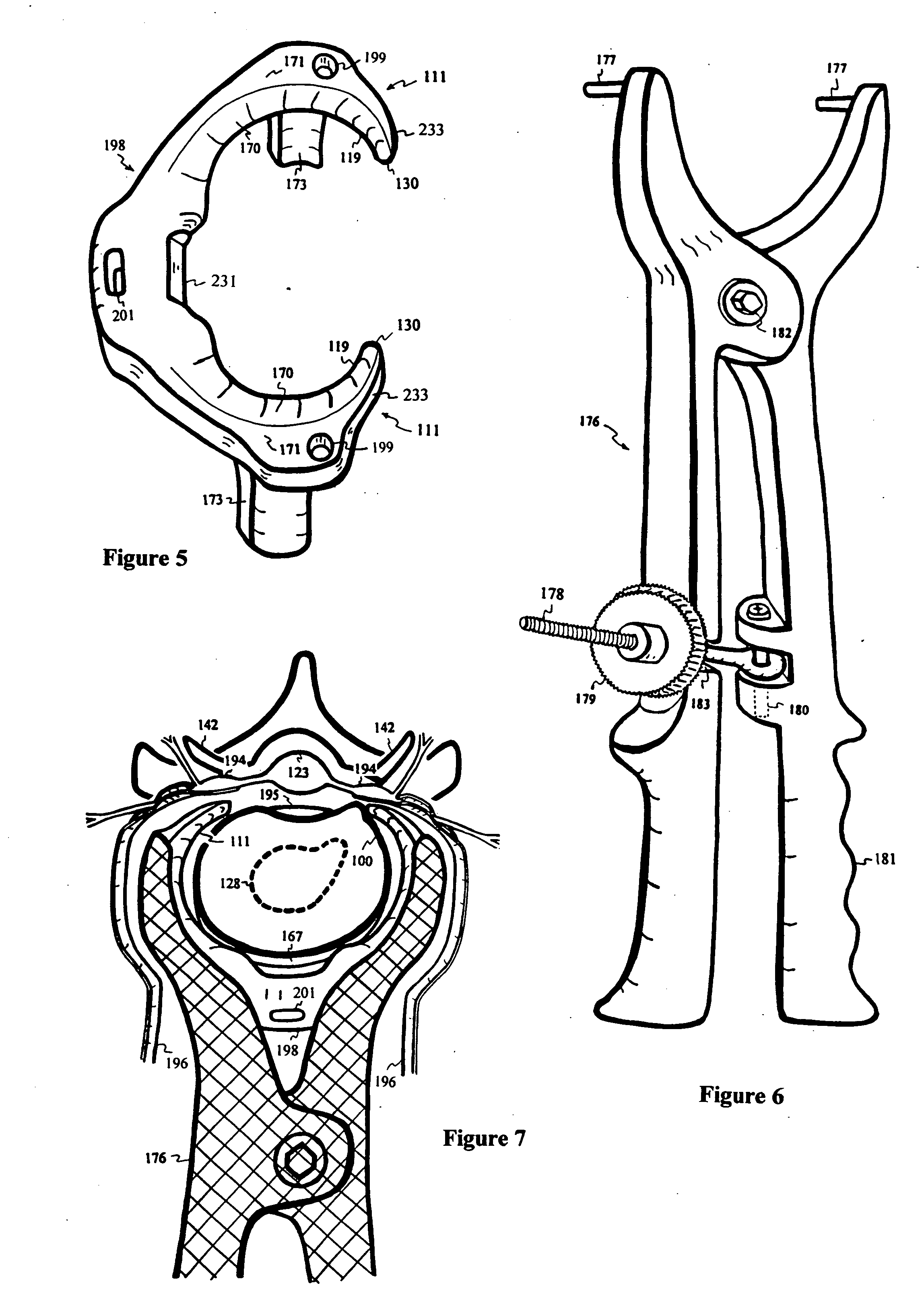
[0125] FIG. 5 shows an elastic intervertebral disc clamp 198 with an annular contact surface 119, a sloped surface 170, a plateau surface 171 and stops 1...


PUM


Abstract

A saddle-shaped compression device and methods of fastening a dysfunctional intervertebral disc are used to (1) compress a protrusion to alleviate nerve impingement, (2) fortify the annulus to stabilize a motion segment, (3) minimize the inward / outward bulging and delamination of the annulus, (4) atrophy the nerve to treat discogenic pain, (5) correct the curvature of spinal deformities, (6) elevate the disc space to treat spinal stenosis, and (7) seal the seepage of nucleus pulposus from a herniated disc.

Description

[0001] This invention relates to devices and methods for treating disc protrusion, segmental instability, spinal stenosis, scoliosis or kyphosis by compressing or thickening the intervertebral disc. The invention also proposes a device and method to promote annular regeneration and adhesion onto the end plate to accelerate healing of the dysfunctional disc and spondylolisthesis.BACKGROUND, EXISTING SURGICAL PRACTICES AND PRIOR INVENTIONS[0002] Low-back pain is one of the most prevalent, costly and debilitating ailments afflicting mankind. Seventy to eighty-five percent of all people have back pain at some time in their life. Symptoms are most common among middle-aged adults and are equally common among both men and women. Back pain related to disc disorders, however, is more prevalent among men. The recurrence rate of low back pain ranges from 20% to 44% annually, with lifetime recurrences of 85% (National Institute of Health Guide, Vol. 26, 16, May 16, 1997).[0003] Low back pain is...

Claims


Application Information

Patent Timeline
IPC IPC(8): A61B17/00A61B17/17A61B17/70A61F2/44
CPCA61B17/1757A61B17/70A61F2002/4435A61B2017/00867A61B2017/00004
Inventor YEUNG, JEFFREY E.YEUNG, TERESA T.
Owner YEUNG JEFFREY E
Learn More