Self-pinned in-stack bias structure for magnetoresistive read heads

Inactive Publication Date: 2004-06-10
IBM CORP
View PDF9 Cites 30 Cited by
  • Summary
  • Abstract
  • Description
  • Claims
  • Application Information

AI Technical Summary

Problems solved by technology

When the CPP sensor is used, magnetic stabilization of the free (sense) layer using hard bias layers in the end regions to provide lon

Method used


Image

  • Self-pinned in-stack bias structure for magnetoresistive read heads
  • Self-pinned in-stack bias structure for magnetoresistive read heads
  • Self-pinned in-stack bias structure for magnetoresistive read heads

Examples


first embodiment

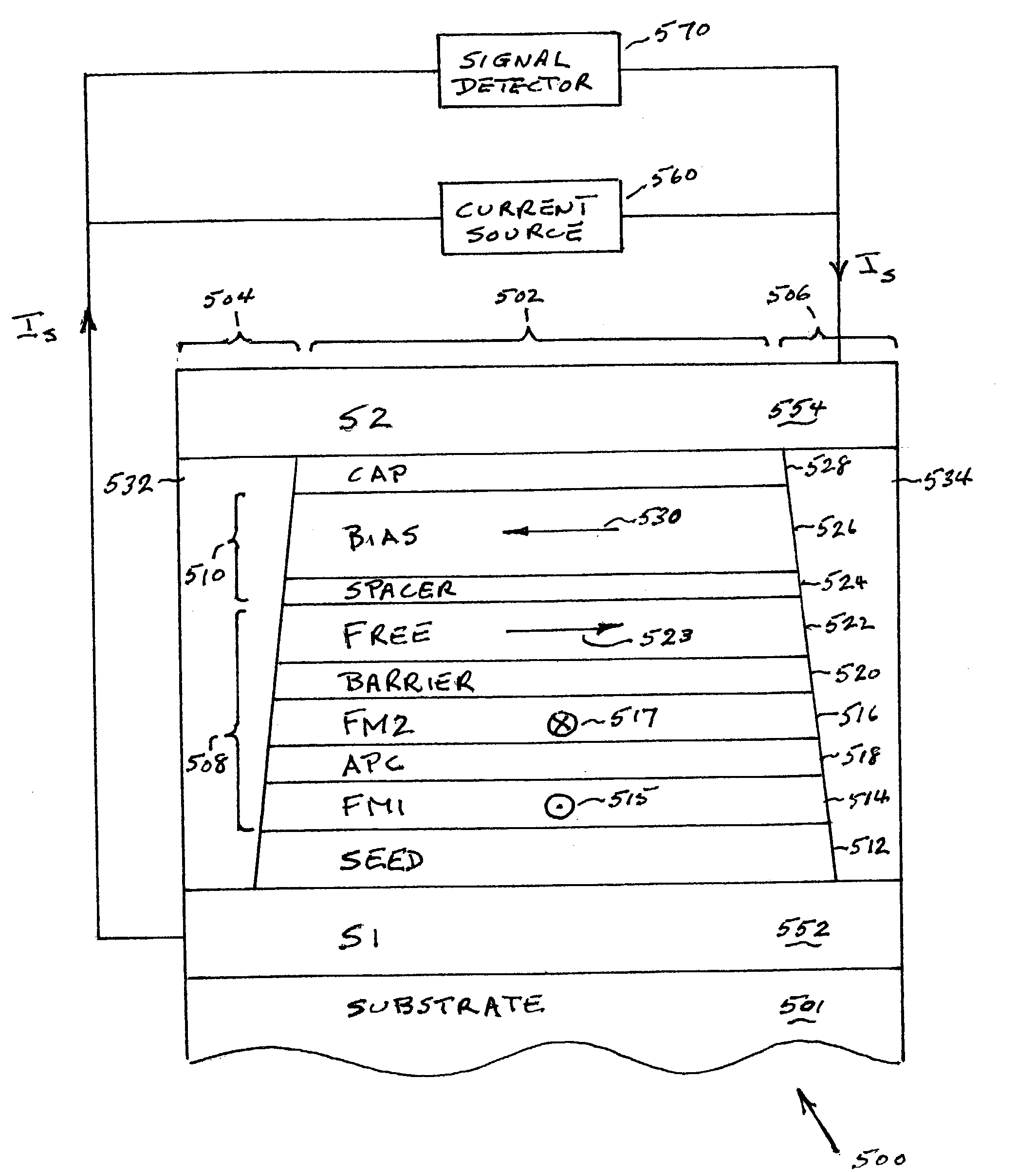
[0037] FIG. 5 depicts an air bearing surface (ABS) view, not to scale, of a MTJ sensor 500 having a self-pinned in-stack bias layer according to the present invention. The MTJ sensor 500 comprises end regions 504 and 506 separated from each other by a central region 502. The substrate can be any suitable substrate including glass, semiconductor material, or a ceramic material such as alumina (Al.sub.2O.sub.3). The active region of the MTJ sensor comprises a MTJ stack 508 and a longitudinal bias stack 510 formed in the central region 502. The seed layer 512 is a layer deposited to modify the crystallographic texture or grain size of the subsequent layers. The MTJ stack 508 sequentially deposited over the seed layer comprises a first ferromagnetic layer (FM1) 514, an antiparallel coupling (APC) layer 518, a second ferromagnetic layer (FM2) 516, a tunnel barrier layer 520 and a ferromagnetic free layer 522. The APC layer 518 is formed of a nonmagnetic material, preferably ruthenium (Ru...

second example

[0048] FIG. 6 shows an air bearing surface view (ABS) view, not to scale, of a CPP spin valve (SV) sensor 600 according to a second embodiment of the present invention. The SV sensor 600 differs from the MTJ sensor 500 depicted in FIG. 5 in having a CPP SV stack 608 in place of the MTJ stack 508. The active region of the SV sensor comprises the SV stack 608 and the longitudinal bias stack 510 formed in the central region 502. The SV stack 608 sequentially deposited over the seed layer 512 comprises a first ferromagnetic layer (FM1) 514, an antiparallel coupling (APC) layer 518, a second ferromagnetic layer (FM2) 516, a conductive spacer layer 620 and a ferromagnetic free layer 522. The conductive spacer layer 620, preferably formed of copper having a thickness of about 20 .ANG., replaces the insulating tunnel barrier layer 520 of the MTJ sensor 500 of the first example. The APC layer 518 is formed of a nonmagnetic material, preferably ruthenium (Ru), that allows the FM1 and FM2 laye...


PUM


Abstract

A current-perpendicular-to-the plane magnetoresistive sensor with a self-pinned in-stack longitudinal bias structure is provided comprising a ferromagnetic bias layer formed of material having a negative magnetostriction coefficient and a spacer layer for antiparallel coupling to a free layer. The negative magnetostriction of the bias layer interacts with the lapping-induced stress anisotropy of the sensor stack to provide strong pinning of the magnetization of the bias layer in a direction parallel to the ABS and antiparallel to the direction of the magnetization of the free layer. Magnetostatic coupling of the bias layer magnetization with the free layer provides a longitudinal bias field to stabilize the free layer magnetization.

Description

[0001] 1. Field of the Invention[0002] This invention relates in general to magnetoresistive sensors for reading information signals from a magnetic medium and, in particular to a magnetoresistive read head with a self-pinned in-stack pinned bias structure for free layer domain control.[0003] 2. Description of Related Art[0004] Computers often include auxiliary memory storage devices having media on which data can be written and from which data can be read for later use. A direct access storage device (disk drive) incorporating rotating magnetic disks is commonly used for storing data in magnetic form on the disk surfaces. Data is recorded on concentric, radially spaced tracks on the disk surfaces. Magnetic heads including read sensors are then used to read data from the tracks on the disk surfaces.[0005] In high capacity disk drives, magnetoresistive (MR) read sensors, commonly referred to as MR sensors, are the prevailing read sensors because of their capability to read data from ...

Claims


Application Information

Patent Timeline
IPC IPC(8): G11B5/39G11C11/16
CPCB82Y10/00B82Y25/00G11C11/16G01R33/098G11B5/3906G01R33/093
Inventor GILL, HARDAYAL SINGH
Owner IBM CORP
Why Eureka
Try Eureka