Apparatus for making dental inlays and the like

Inactive Publication Date: 2004-06-17
CERAMATIC DENTAL
View PDF9 Cites 3 Cited by
  • Summary
  • Abstract
  • Description
  • Claims
  • Application Information

AI Technical Summary

Benefits of technology

[0007] Owing to the second sensing unit and the second milling unit associated therewith, said milling unit being intended especially for quick machining, the production time is considerably reduced as is the need for maintaining the apparatus, since the life of the shank-end mill of the first milling unit increase significantly as it only has to perform the fine mmilling, the second milling unit having performed the rough-machining.
[0009] This solution allows, in a simple manner, simultaneous machining of the blank from two sides, more specifically, a preparatory rough-machining carried out by the second milling unit on one side of the blank and a final finishing of the rough-machined surface on the other side of the blank.
[0011] This solution ensures, in a particularly simple manner, both the necessary synchronization between the two spindles and the similarly necessary relative alignment of these.
[0013] This solution, too, aims at ensuring a maintained synchronization between the two spindles and allows, in a simple manner, rotational driving thereof by means of a motor, which is integrated into the bearing housing and displaceable together with said bearing housing.
[0017] By fixing said bearing housings in a fixed corner of a precision manufactured sectional element, the mounting of the apparatus is greatly facilitated, since no readjustment is required with this mode of mounting.
[0019] An advantage of this solution is that it reduces the risk of undersirable vibrations being transferred to the second milling unit, thus improving the possibilities of obtaining a high degree of accuracy.

Problems solved by technology

The prior-art device has apparent drawbacks as far as user-friendless and, particularly, speed are concern.

Method used


Image

  • Apparatus for making dental inlays and the like
  • Apparatus for making dental inlays and the like
  • Apparatus for making dental inlays and the like

Examples


Embodiment Construction

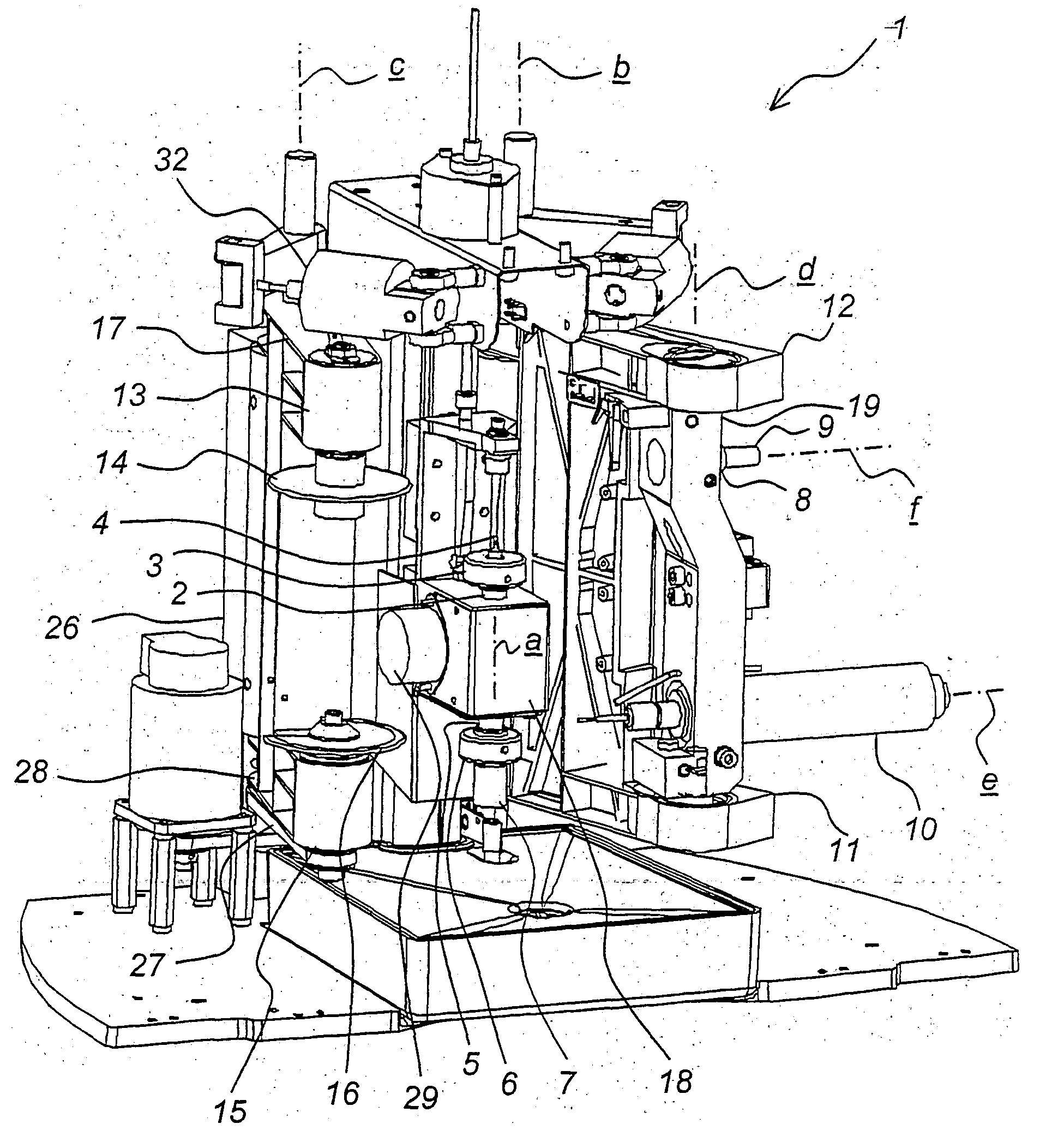
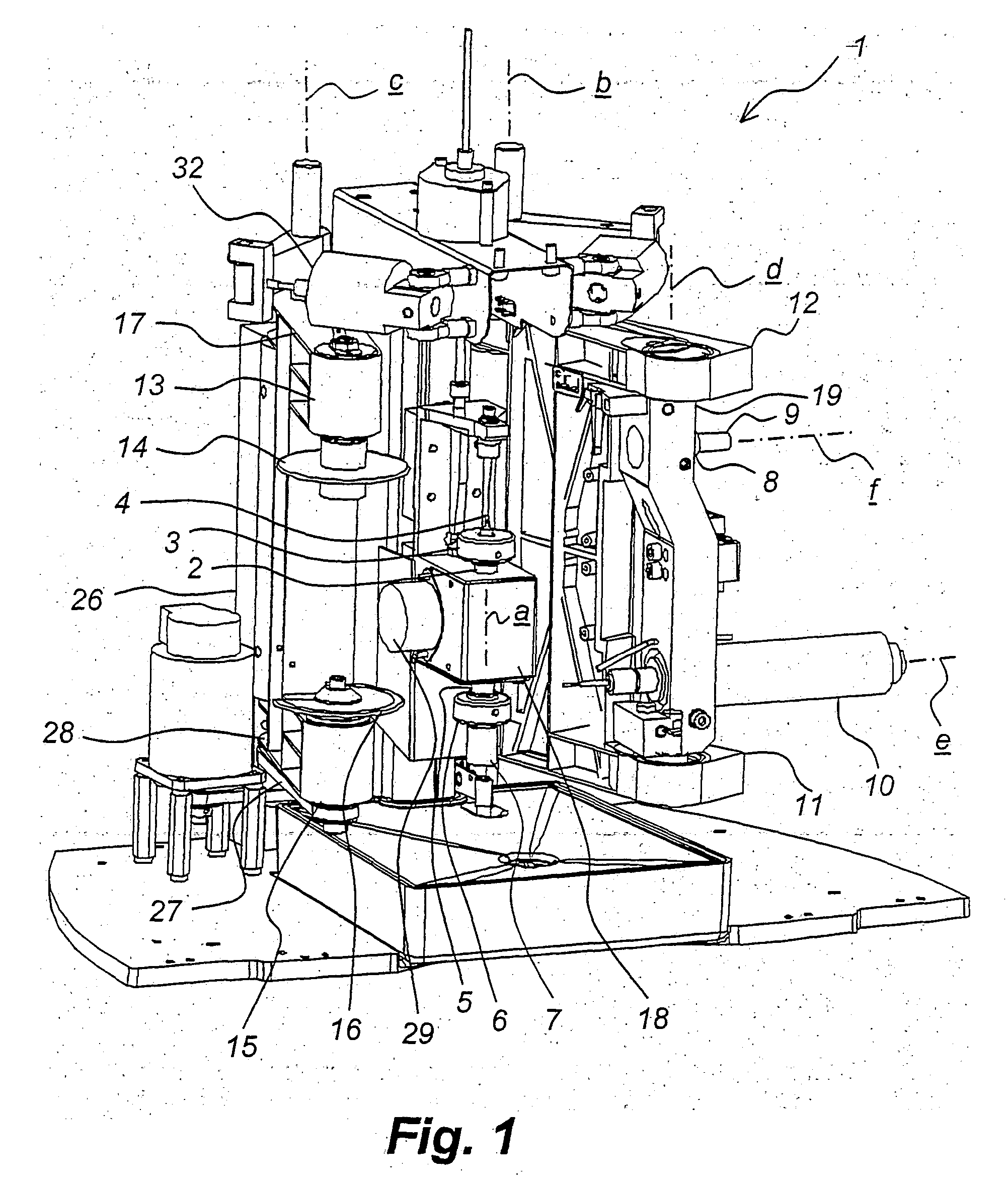
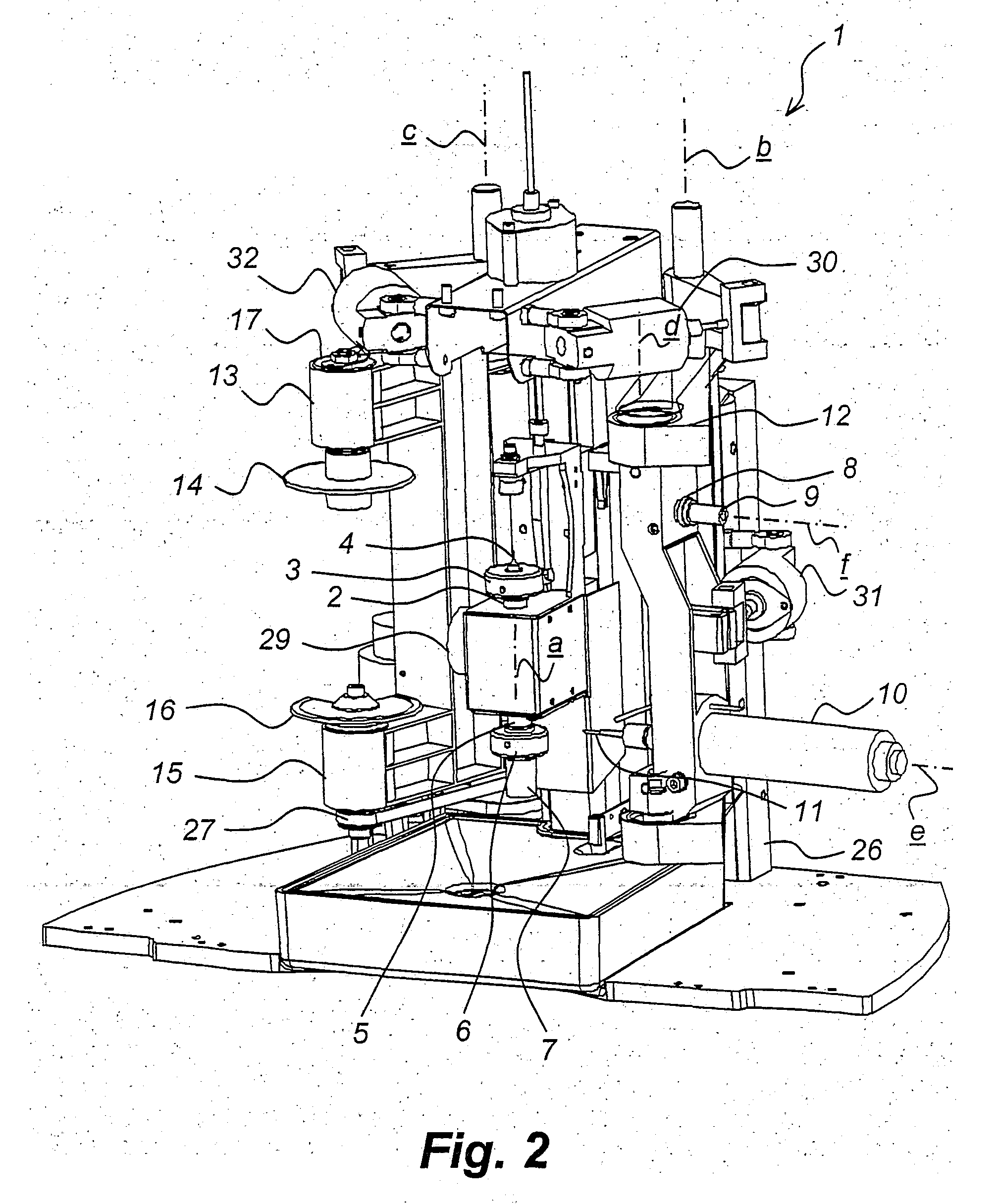
[0026] The same reference numerals are used throughout to designate corresponding parts of the apparatus illustrated in FIGS. 1-5. The apparatus 1 is intended for making dental inlays of the type described by way of introduction, which is well known to a person skilled in the art. Thus, no detailed description of such a dental inlay, the production of an inlay original or the attachment of the inlay to a prepared tooth by means of an adhesive cement is required.

[0027] Some of the parts that are suggestive of a prior-art apparatus (WO96 / 05781) are a rotatable first spindle 2, which is adapted to hold the original 4 with the aid of a fixing means 3 arranged at the end of the spindle 2, and a rotatable second spindle 5, which is aligned with the first spindle 2 and adapted to hold the blank 7 with the aid of a fixing means 6.

[0028] Other parts are a first sensing unit 8, which is adapted to scan the original 4 with a probe 9, and a first milling unit 10 which is adapted to mill the bla...


PUM


Abstract

An apparatus (1) for making dental inlays or the like by copy milling a blank (7) based on an original (4) comprises a first spindle (3), which is adpated to hold the original (4) and a second spindle (5), which is aligned with the first spindle (2) and adapted to hold the blank (7). A first sensing unit (8) is adapted to scan the original (4) with a probe (9), and a first milling unit (10) is adapted to mill the blank (7) by means of a shank-end mill (11) to form a dental inlay or the like whose shape corresponds to that of the orignal (4) scanned by the probe (9). A second sensing unit (13) is adapted to carry out a rough scan of the original (4) before the first sensing unit (8) by means of a rotatable disc (14), and a second milling unit (15) is adapted to machine the blank (7), while the disc (14) scans the original (4), by means of a milling disc (16) whose size corresponds to that of the disc (14) to create a shape which roughly corresponds to that of the original (4).

Description

[0001] The present invention relates to an apparatus for making dental inlays or the like by copy milling a blank based on an original, for example in the form of an impression of a tooth cavity to be filled, said apparatus comprising a rotatable first spindle, which is adapted to hold the original with the aid of a fixing means arranged at the end of the spindle; a rotatable second spindle, which is aligned with the first spindle and adapted to hold the blank with the aid of a fixing means arranged at the end of the second spindle, the operation of said spindles being synchronized; a first sensing unit, which is adapted to scan the original with a probe; and a first milling unit, which is adapted to mill the blank, while the probe scans the original, by means of a shank-end mill to form a dental inlay or the like whose shape corresponds to that of the original scanned by the probe, the first sensing unit and the first milling unit being mounted on a common first holder, which is pi...

Claims


Application Information

Patent Timeline
IPC IPC(8): A61C13/00A61C13/38
CPCA61C13/0009A61C13/0022Y10T409/307784Y10T409/305656Y10T409/301792Y10T409/307168
Inventor SJOSTEDT, LENNARTDAHR, ANDREAS
Owner CERAMATIC DENTAL
Why Eureka
Try Eureka