Modified, field installable, field adjustable flexible angled boot for multi-conductor cables and process for installing the same

a multi-conductor cable and flexible angle technology, applied in the direction of optical elements, coupling device connections, instruments, etc., can solve the problems of cable re-straightening, cable elasticity is very stiff, and it is difficult to easily troubleshoot and repair the system, and the cable portion is very sti

a multi-conductor cable and flexible angle technology, applied in the direction of optical elements, coupling device connections, instruments, etc., can solve the problems of cable re-straightening, cable elasticity is very stiff, and it is difficult to easily troubleshoot and repair the system, and the cable portion is very sti

US20040121646A1Inactive Publication Date: 2004-06-24EMERSON TELECOMM PROD

Image

  • Modified, field installable, field adjustable flexible angled boot for multi-conductor cables and process for installing the same
  • Modified, field installable, field adjustable flexible angled boot for multi-conductor cables and process for installing the same
  • Modified, field installable, field adjustable flexible angled boot for multi-conductor cables and process for installing the same

Examples


Embodiment Construction

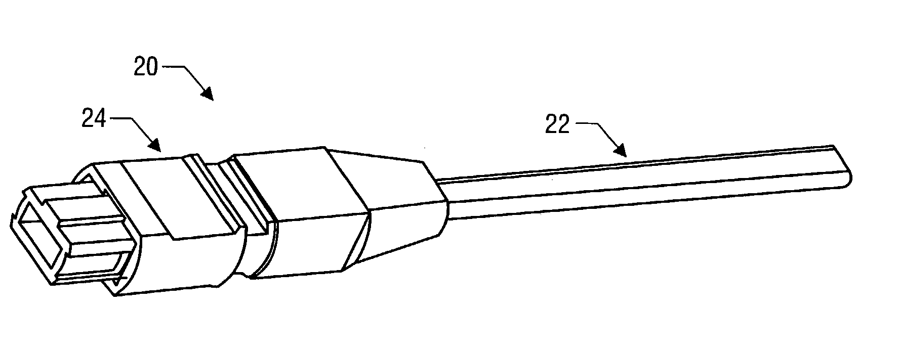
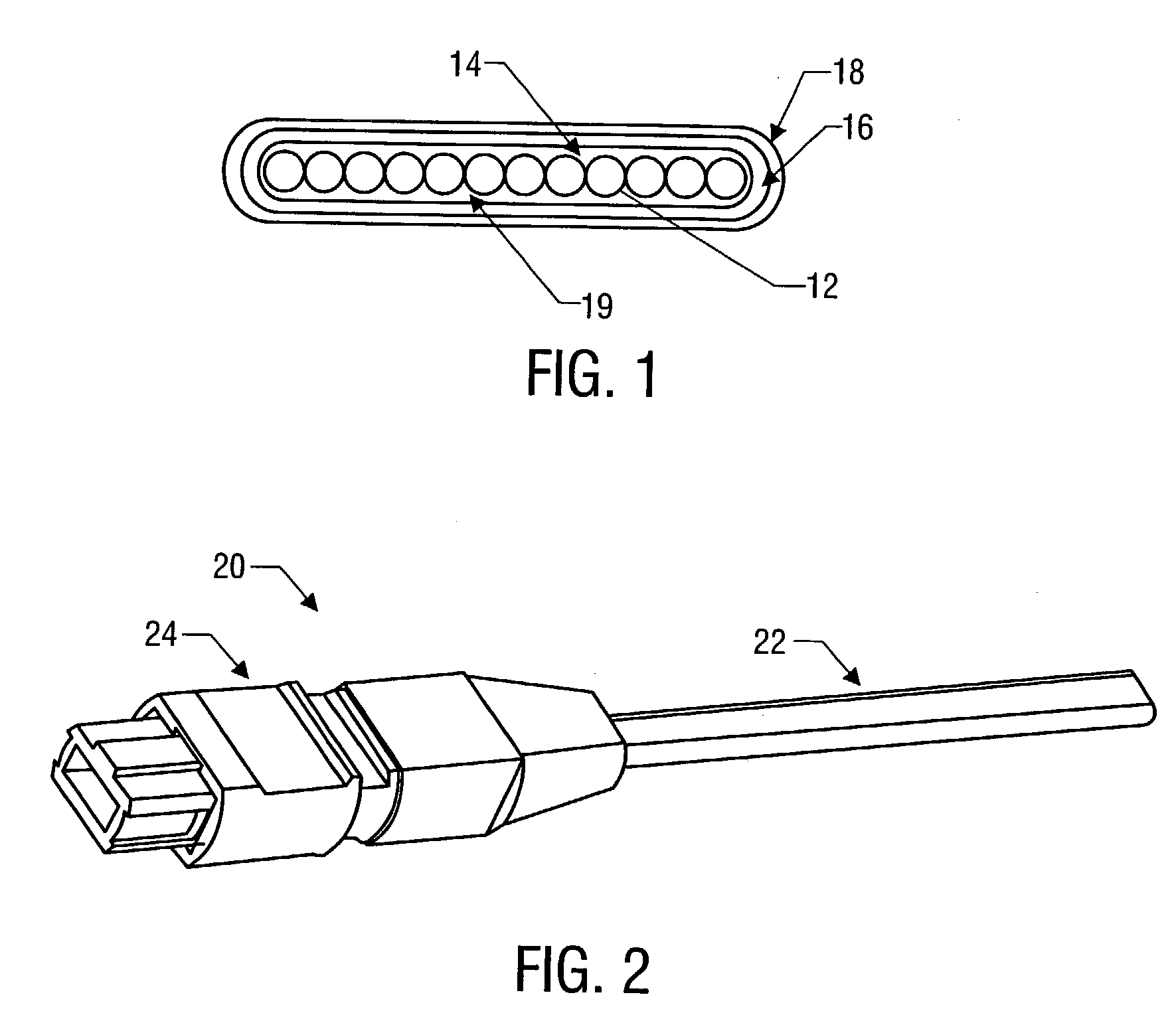
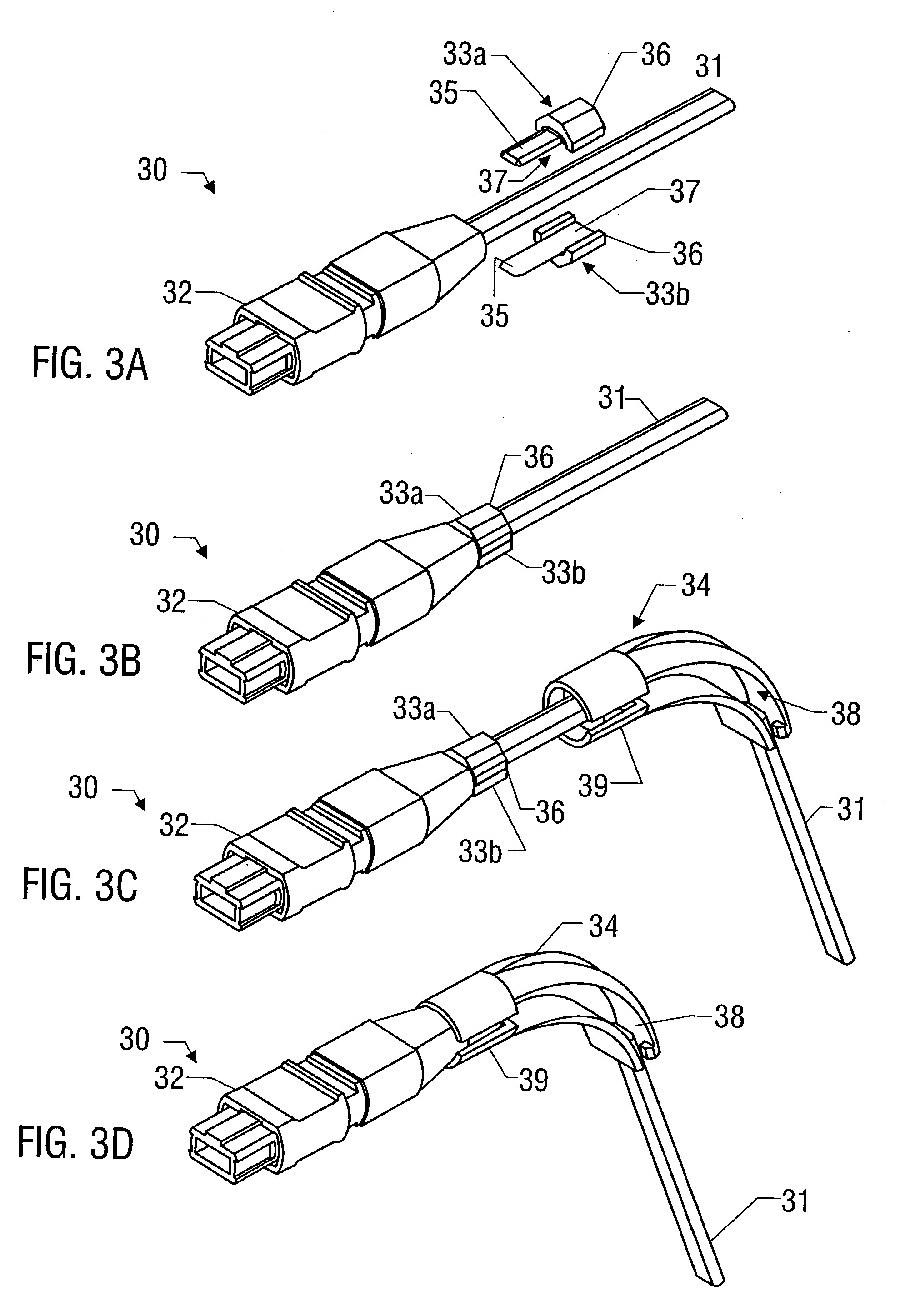
[0039] Referring to the drawings, in particular to FIGS. 3A-3D, a connection cable assembly 30 is illustrated for use in applications where a connection cable is to be bent at or after initial installation. In general, the cable assembly 30 includes a multi-conductor cable component 31 that may be, for example, a multi-optical fiber ribbon cable as described above in connection with FIG. 1. The cable assembly further includes a connector 32 that, in the illustrated exemplary embodiment, is an MPO-type connector having a rectangular opening as described above in connection with FIG. 2. Coupled to the connector 32 are cable clips 33a and 33b and coupled to the cable clips 33a-33b is an angled boot 34. The outer exterior surface of the cable clips 33a and 33b is received in the interior of the angled boot 34 such that the angled boot 34 maintains a controlled and protective bend of the ribbon cable 31 as it exits the connector 32. The angle of the bend defined by the angled boot 34 is ...


PUM


Abstract

The present disclosure relates to connector assemblies for use with multi-conductor connection cables. More specifically, the present disclosure relates to a flexible angle configurable boot assembly for use with a multi-conductor cable where the angle configurable boot defines an area for receiving the multi-conductor cable for positioning the cable at a known angle and / or orientation with respect to the flexible angle configurable boot in at least one location, and where the angle configurable boot may be coupled to the cable connector in one or a plurality of alternate orientations. The present disclosure also relates to a process for installing such a flexible angle configurable boot assembly.

Description

[0001] The present application is a Continuation-In-Part of pending U.S. patent application Ser. No. 10 / 323,300 filed Dec. 18, 2002. The contents of the foregoing application are incorporated herein by reference.FIELD OF THE DISCLOSURE[0002] The present disclosure relates to connector assemblies for use with multi-conductor connection cables. More specifically, the present disclosure relates to a flexible angle configurable boot assembly for use with a multi-conductor cable where the angle configurable boot defines an area for receiving the multi-conductor cable for positioning the cable at a known orientation or angle with respect to the angled boot in at least one location, and where the angled boot may be coupled to the connector in one or a plurality of alternate orientations. The present disclosure also relates to a process for installing such a flexible angle configurable boot assembly.BACKGROUND OF THE DISCLOSURE[0003] Modern information systems such as telecommunication syst...

Claims


Application Information

Patent Timeline
24 Jun 2004
Publication
US20040121646A1
IPC
G02B6/38; H01R9/03; H01R13/56
CPC
G02B6/3829; G02B6/3885; H01R13/562; H01R9/03; G02B6/3887; G02B6/38875
Inventors
IAMARTINO, JOSEPH; MANNELL, MATTHEW J.