Contact sensitive device

a sensitive device and contact technology, applied in the direction of liquid/fluent solid measurement, instruments, machines/engines, etc., can solve the problems of high damping, relatively high stiffness, and inability to meet the above-phase equation

Inactive Publication Date: 2004-07-08
GOOGLE LLC +1
View PDF37 Cites 128 Cited by
  • Summary
  • Abstract
  • Description
  • Claims
  • Application Information

AI Technical Summary

Problems solved by technology

If the coherence condition is not satisfied, the above phase equation may not be satisfied.
These may have a high degree of damping and relatively high stiffness.

Method used


Image

  • Contact sensitive device
  • Contact sensitive device
  • Contact sensitive device

Examples


Embodiment Construction

)

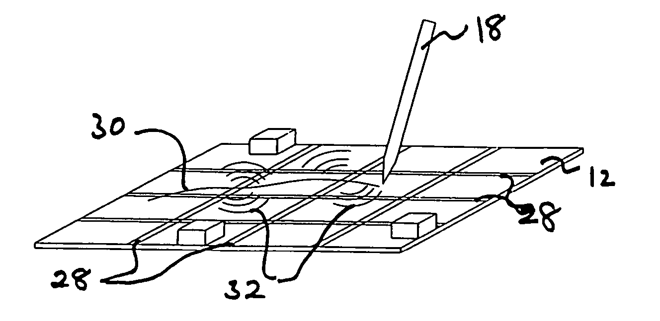
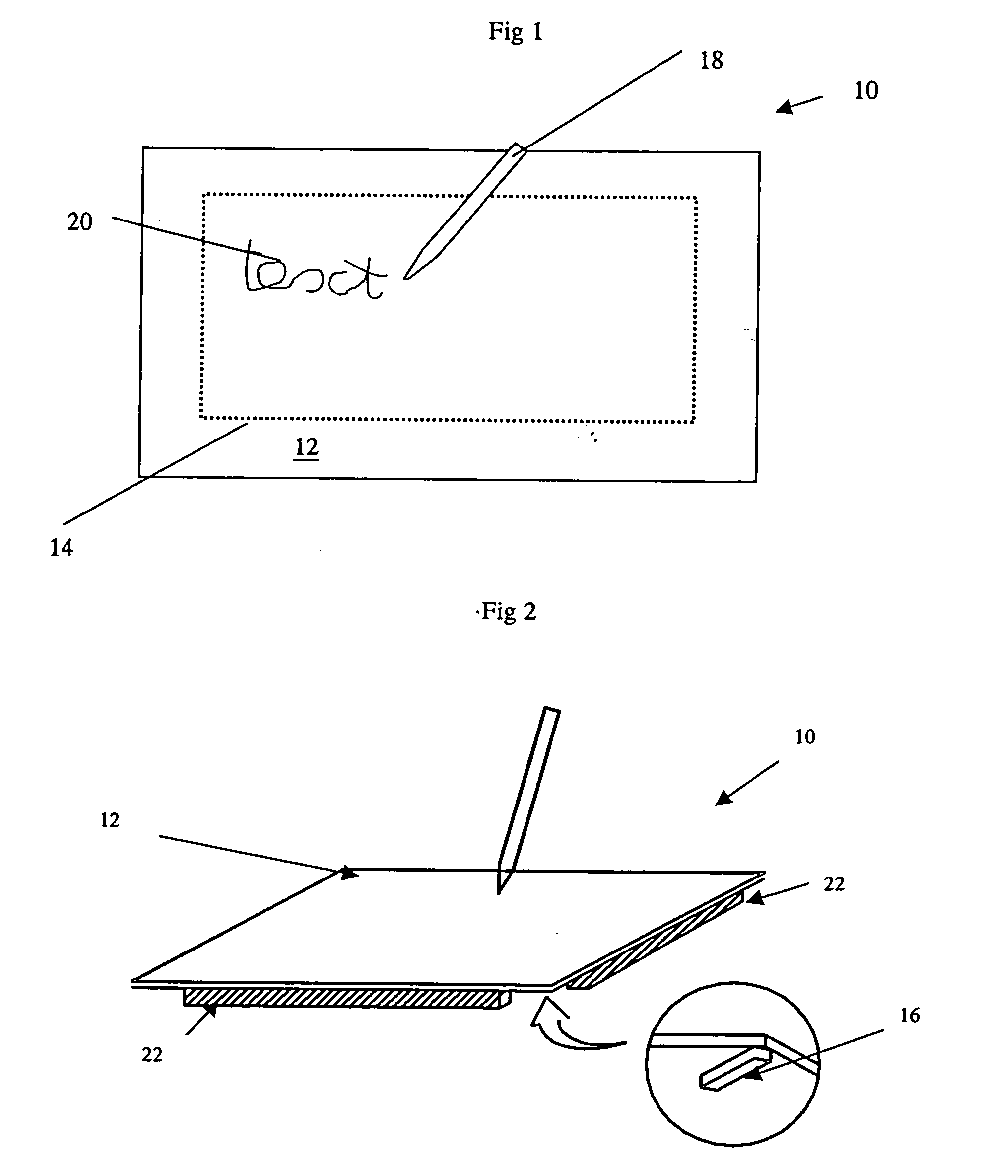
[0062] FIG. 1 shows a contact sensitive device 10 comprising a transparent touch sensitive plate 12 mounted in front of a display device 14. The display device 14 may be in the form of a television, a computer screen or other visual display device. A stylus 18 in the form of a pen is used for writing text 20 or other matter on the touch sensitive plate 12.

[0063] The transparent touch sensitive plate 12 is a member, e.g. an acoustic device, capable of supporting bending wave vibration. As shown in FIG. 2, four sensors 16 for measuring bending wave vibration in the plate 12 are mounted on the underside thereof. The sensors 16 are in the form of piezoelectric vibration sensors and are mounted one at each corner of the plate 12. At least one of the sensors 16 may also act as an emitting transducer for exciting bending wave vibration in the plate. In this way, the device may act as a combined loudspeaker and contact sensitive device.

[0064] In the following applications, U.S. patent appl...


PUM


Abstract

A contact sensitive device includes a member capable of supporting bending waves and a plurality of sensors mounted on the member for measuring bending wave vibration in the member. The sensors measure the bending wave signals and by calculating a phase angle for each measured bending wave signal and a phase difference between the phase angles of least two pairs of sensors so that at least two phase differences are calculated, the location of the contact can be determined.

Description

CROSS-REFERENCE TO RELATED APPLICATION(S)[0001] This application claims the benefit under 35 U.S.C. .sctn. 119(e) of application No. 60 / 432,024, filed Dec. 10, 2002, which application is incorporated herein by reference.[0002] 1. Field of the Invention[0003] The invention relates to contact sensitive devices.[0004] 2. Description of the Related Art[0005] Visual displays often include some form of touch sensitive screen. This is becoming more common with the emergence of the next generation of portable multimedia devices such as palm top computers. The most established technology using waves to detect contact is Surface Acoustic Wave (SAW), which generates high frequency waves on the surface of a glass screen, and their attenuation by the contact of a finger is used to detect the touch location. This technique is "time-of-flight", where the time for the disturbance to reach one or more sensors is used to detect the location. Such an approach is possible when the medium behaves in a n...

Claims


Application Information

Patent Timeline
Patent Type & Authority Applications(United States)
IPC IPC(8): G06F3/033G06F3/041G06F3/043
CPCG06F3/0418G06F3/0436G06F3/043
Inventor SULLIVAN, DARIUS MARTINROLAND HILL, NICHOLAS PATRICK
Owner GOOGLE LLC
Why Eureka
Try Eureka