Radar beam scanning method, on-vehicle radar apparatus and radar scanning computer program

a radar and computer program technology, applied in the direction of antennas, instruments, movable body antenna adaptation, etc., can solve the problems of remarkably lowering the detectable distance and detection accuracy, the tilt angle cannot always be rotated to the prescribed angle, and the radar beam is apt to miss the targ

Inactive Publication Date: 2004-07-29
DENSO CORP
View PDF8 Cites 41 Cited by
  • Summary
  • Abstract
  • Description
  • Claims
  • Application Information

AI Technical Summary

Problems solved by technology

However, when the radar beam is over-collimated, the radar beam is apt to miss the target due to a vertical inclination during an acceleration & deceleration and during carrying a heavy load.
Thus, the conventional on-vehicle radar have a disadvantage that the target is missed or the reflection from the target is decreased, thereby remarkably lowering a detectable distance and detection accuracy.
However, JP4-276582A has a disadvantage that the tilt angle can not always be rotated to a prescribed angle, because the road surface reflection depend upon the road surface state, ground topology and distance between the vehicle and the road surface from which the radar bea...

Method used


Image

  • Radar beam scanning method, on-vehicle radar apparatus and radar scanning computer program
  • Radar beam scanning method, on-vehicle radar apparatus and radar scanning computer program
  • Radar beam scanning method, on-vehicle radar apparatus and radar scanning computer program

Examples


embodiment 1

[0056] Embodiment 1

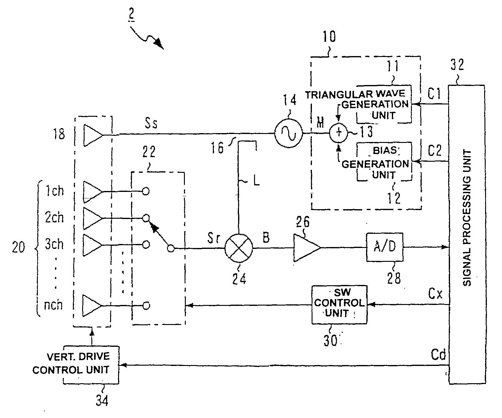
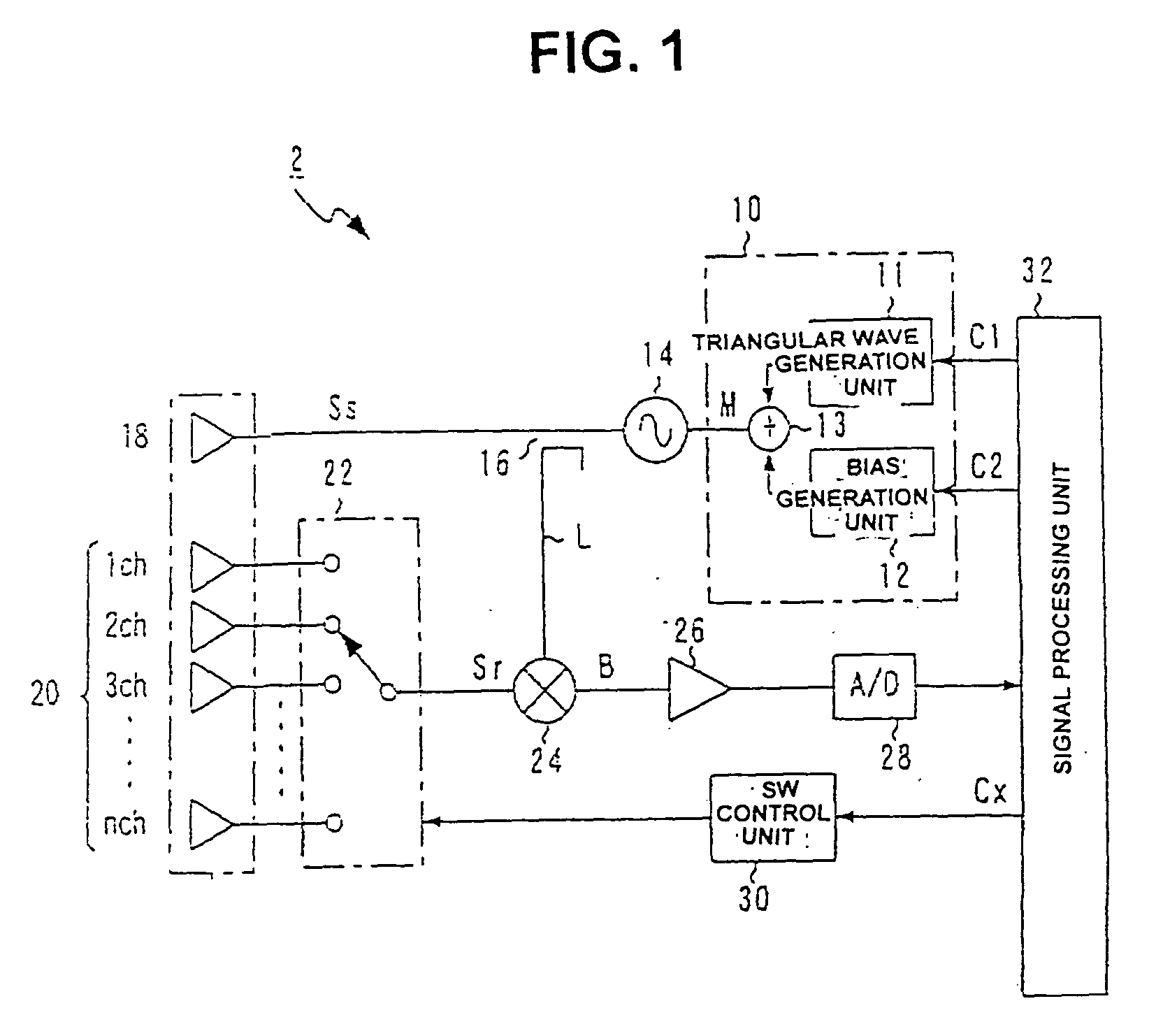
[0057] The radar apparatus 2 of Embodiment as shown in FIG. 1 comprises: a modulation signal generation unit 10 for generation a modulation signal "M" in accordance with modulation instructions C1 and C2; a VCO 14 for varying an oscillation frequency in accordance with "M"; a distributor 16 for distributing an output from the VCO 14 into a transmission signal Ss and local signal "L"; a transmission antenna 18 for radiating an electromagnetic wave in accordance with the Ss; a reception antenna 20 including "n" unit antennas for receiving the reflected electromagnetic wave; a reception switch 22 for selecting one of the "n" unit antennas for receiving a reception signal Sr; a mixer 24 connected with the switch 22 for mixing Sr and "L" in order to generate a beat signal "B"; an amplifier 26 for amplifying "B"; an A / D converter 28 for converting the amplified "B" into a digital data; a SW control unit 30 for controlling the reception switch 22 in accordance with a mod...

embodiment 2

[0087] Embodiment 2

[0088] The structure of the reception antenna 20, the operation of the SW control unit 30 and content of the processing of the signal processing unit 32 in Embodiment 2 are different from those in Embodiment. Therefore, the differences of Embodiment 2 from Embodiment 1 are mainly explained.

[0089] Although the transmission antenna 18 and reception antenna 20 are the travelling wave excitation antennas (unit antennas constructed by antenna elements "E") formed on a substrate "P" in Embodiments 1 and 2, the distances between the antenna elements "E" are slightly different with each other, as shown in FIG. 7A. There are shown in FIG. 7A only 4 ch, 5 ch and 6 ch of the "n" unit antennas. Concretely, the inter-devices distances (distances between the antenna elements "E") are decided in such a manner that a tilt angle .theta. of an unit antenna in the reception antenna 20 is different with each other by .quadrature..theta. expressed by formula (1).

.DELTA..theta.=.theta....

embodiment 3

[0103] Embodiment 3

[0104] Embodiment 3 partially differs from Embodiment 2 in the inter-devices distance in the antenna elements "E", the vertical scan at S110 and horizontal scan at S130.

[0105] The inter-element distance (IED) is decided, as shown in FIG. 11, in such a manner that: the tilt angle .theta..sub.A for the frequency f.sub.M of ch 1 with the narrowest IED is almost the same as .theta..sub.B for f.sub.L of ch "n" with the widest IED; and moreover, .theta..sub.C for f.sub.M of ch "n" with the widest IED is almost the same as .theta..sub.D for f.sub.H of ch 1 with the narrowest IED.

[0106] At S110 modified for Embodiment 3, the vertical scan mode is turned on by the mode designation instruction Cx, thereby operating the VCO 14 at, e.g., f.sub.L (one of the three frequencies f.sub.L, f.sub.M, and f.sub.H) in accordance with the modulation instructions C1 and C2. Thus, during sequentially selecting every channel 1 ch to "n" ch, the sampling data of all the channels (ch 1 to ch...


PUM


Abstract

In the on-vehicle radar apparatus of the present invention, the vertical scanning width of the radar beam is narrowed, before the horizontal scanning, thereby avoiding unnecessary data processing and improving the data processing efficiently. Further, the SIN ratio of the target detection signal is increased, thereby stabilizing the distance detection and its accuracy. The vertical scanning antenna is a single travelling wave excitation antenna (TWEA) constructed by a plurality of antenna elements. At the same time, the horizontal scanning antenna is a multi-channel antenna wherein a plurality of TWEAs is assigned to a plurality of horizontal directions. The horizontal scanning angle is arbitrarily widened by increasing the number of TWEAs.

Description

[0001] 1. Field of the Invention[0002] The present invention relates to a radar beam scanning method, on-vehicle radar apparatus and radar scanning computer program, for detecting a target object which reflects an electromagnetic waves radiated from the frequency-modulated continuous wave (FMCW) radar apparatus mounted on a automotive vehicle.[0003] 2. Description of the Related Art[0004] On-vehicle radar apparatuses for detecting a distance, relative speed and direction of such a target around the vehicle as an obstacle or precedent vehicle have been widely employed in order to control a crash prevention and tracking travelling.[0005] The radar apparatus of this kind is fixed at the vehicle front in such a manner that the electromagnetic wave beam for detecting the target is parallel to the road surface. Further, the radar beam is preferably collimated along the vertical direction, thereby suppressing a reflection from the road surface.[0006] However, when the radar beam is over-co...

Claims


Application Information

Patent Timeline
IPC IPC(8): G01S7/02G01S7/03G01S7/35G01S7/40G01S13/34G01S13/42G01S13/66G01S13/87G01S13/931H01Q1/32H01Q3/04
CPCG01S7/032G01S7/35G01S7/4026G01S13/345G01S13/426G01S13/66G01S2007/4034G01S13/931H01Q1/3233H01Q3/04G01S7/4056G01S2007/4091G01S13/87G01S7/4034G01S7/4091
Inventor KATAYAMA, TETSUYATANAKA, YUICHI
Owner DENSO CORP
Why Eureka
Try Eureka